
Reflex 75T Conventional Flue User Installation Manual

20
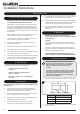
Installation Instructions
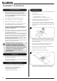
5b.3 Connect the ue and install the appliance into the aperture.
At the same time ensure that the gas pipe passes through
the silicon panel at the back of the appliance.
Provide electric services into the void on the right hand
side.
It is necessary to be able to disconnect the
appliance from the mains electrical supply after
installation.
This may be achieved by an accessible plug or by
incorporating a switch into the fixed wiring in
accordance with the rules in force.
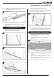
5b.4 Slide the metal plate, previously removed, over the gas pipe
and secure with a screw, see Diagram 18.
18
Screw
Metal Plate
Gas Supply
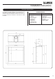
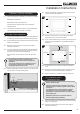
5b.5 Secure the appliance through the 6 xing holes using the
screws provided, see Diagram 16.
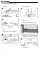
5b.6 The appliance ange should sit ush to the brickwork and
the edge should sit proud of the wall, see Diagram 19.
19
Appliance
Edge
Masonry
Brickwork
Appliance
Outer Casing
Heat Resistant
Plaster
Appliance Flange
5b.7 The subframe for the decorative front can now be tted by
following the instructions supplied with the Front.
NOTE: THE SUBFRAME MUST SIT FLUSH TO THE
WALL LEVEL WITH THE APPLIANCE FLANGE.
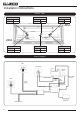
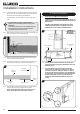
6. Studwork Installation
6.1 DISTANCE TO COMBUSTIBLE MATERIAL
COMBUSTIBLE PARTS OF THE STUDWORK MUST BE
KEPT BEYOND THE MINIMUM DIMENSIONS SHOWN IN
DIAGRAM 20.
PROTECT THE NEAREST STUDWORK WITH NON-
COMBUSTIBLE MATERIAL AND MAINTAIN THESE
DIMENSIONS AT ALL TIMES, SEE DIAGRAM 20.
MINIMUM
COMBUSTIBLE
MATERIAL
CLEARANCES
20
400mm
100mm
400mm
100mm
200mm
200mm
200mm
50mm
Non-combustible
board
Non-combustible
board
12mm
6.2 DO NOT PACK THE VOID AROUND OR ABOVE THE
APPLIANCE WITH INSULATION MATERIALS SUCH AS
MINERAL WOOL.
6.3 THE VOID BUILT FOR THE CASSETTE MUST BE
VENTILATED TO PREVENT A BUILD-UP OF HEAT. IF
THE VOID IS SEALED, THEN YOU MUST FIT VENTS
AT BOTH LOW AND HIGH LEVELS OF A MINIMUM OF
200CM
2
EACH ON BOTH SIDES OF THE ENCLOSURE.
THESE VENTS MUST TAKE COLD AIR FROM THE
ROOM AND RETURN WARM AIR BACK INTO THE
ROOM.
21
75mm