
Reflex 75T Conventional Flue User Installation Manual

18
Installation Instructions
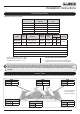
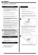
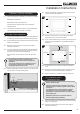
4.5 Remove the 2 screws to remove the Access Panel,
see Diagram 9.
9
Screws
4.6 Remove the 2 screws from the Air Guide, see Diagram 10.
10
Front Screws
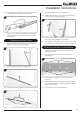
4.7 Lift and rotate the Air Guide upwards from the front edge to
remove.
Note the orientation for reassembly.
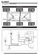
4.8 Disconnect the Mains Lead Plug from the Module, see
Diagram 11.
DO NOT REMOVE THE WIRES FROM THE PLUG.
11
Mains Lead Plug
2 Wing Nuts
4.9 Place the Mains Lead to the side of the right hand bracket to
avoid damage, see Diagram 12.
12
Mains Lead
Plug
Bracket
4.10 Undo the 2 wing nuts, see Diagram 11.
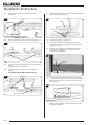
4.11 Lift and slide the Main Control Assembly slightly to the
right and remove through the front of the appliance. Place
carefully to one side.
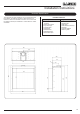
4.12 Undo the screw to remove the metal plate from the back
of the appliance, see Diagram 13. This will need to be
replaced during installation.
13
Screw
Metal Plate
Gas Suppy
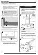
4.13 The gas supply enters through the Silicone Panel located
on the left-hand rear of the outer box; this will need to be slit
with a sharp knife prior to passing the supply pipe through,
see Diagram 14.
14
Note: The Isolation Elbow needs to be attached to the gas
pipe before installation.