
Reflex 75T Conventional Flue User Installation Manual

17
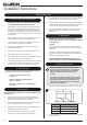
Installation Instructions
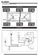
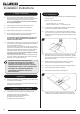
2.9 If a exible liner is to be used check the seal on the inner lip
of the spigot plate is intact. Replace if necessary.
3
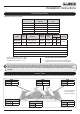
Options 3 and 4 (Studwork with Edge nish or decorative
front) must be tted using the top exit only with rigid twin
wall ue pipe.
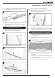
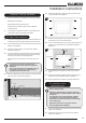
3. Removing the Glass Frame
3.1 Remove the glass door by removing the 2 side trims, see
Diagram 4. These are held on by magnets.
4
3.2 Lift out the bottom slotted trim, see Diagram 5.
5
3.3 Remove the 2 screws at the base of the door, see Diagram 6.
6
Screws
3.4 Pull up the handle at the front, see Diagram 6.
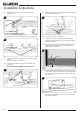
3.5 Whilst supporting the top, lift the door using the handle, up
and over the lower edge, see Diagram 7.
7
3.6 Remove the 2 boxes from the appliance and store safely as
they contain the Log Burners and fuel effects.
3.7 It is advisable to also remove the Liner Panels at this stage
to protect the finish. See Servicing Instructions, Section 19.
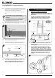
4. Removing the Main Control Assembly
The Main Control Assembly will need to be removed to
install the gas supply.
4.1 Remove the 2 screws from the front of the Mesh Tray,
see Diagram 8.
8
Rear Screws
Front Screws
4.2 Loosen the 3 screws at the rear of the Mesh Tray, see
Diagram 8.
4.3 Slide the Mesh Tray forward slightly to disengage from the
rear screws and carefully lift over the Log Burner Brackets,
Pilot and Cross Lighter.
4.4 Remove through the front of the appliance.