Vogue Range Conventional Flue Log Effect Stove With Upgradeable Control Valve Instructions for Use, Installation and Servicing For use in GB, IE (Great Britain and Republic of Ireland) IMPORTANT THE OUTER CASING, FRONT AND GLASS PANEL BECOME EXTREMELY HOT DURING OPERATION AND WILL RESULT IN SERIOUS INJURY AND BURNS IF TOUCHED. IT IS THEREFORE RECOMMENDED THAT A FIREGUARD COMPLYING WITH BS 8423 (LATEST EDITION) IS USED IN THE PRESENCE OF YOUNG CHILDREN, THE ELDERLY OR INFIRM.
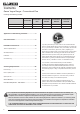
Contents Gazco Vogue Range - Conventional Flue Covering the following models: Model VOGUE MIDI VOGUE MIDI T MIDI VOGUE MIDI MIDLINE VOGUE MIDI T MIDLINE VOGUE MIDI T HIGHLINE Nat Gas 563-123 563-180 563-392 563-224 563-191 LPG 563-426 563-701 563-466 563-493 563-447 Appliance Commissioning Checklist.......................3 User Instructions........................................................4 Installation Instructions...........................................
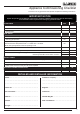
Appliance Commissioning Checklist To assist us in any guarantee claim please complete the following information:- IMPORTANT NOTICE Explain the operation of the appliance to the end user, hand the completed instructions to them for safe keeping, as the information will be required when making any guaranteed claims. FLUE CHECK PASS FAIL 1. Flue Is correct for appliance 2. Flue flow Test 3. Spillage Test GAS CHECK 1. Gas soundness & let by test 2. Standing gas pressure mb 3.
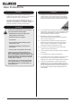
User Instructions Welcome Congratulations on purchasing your Gazco Vogue, if installed correctly Gazco hope it will give you many years of warmth and pleasure for which it was designed. 1. General 1.1 Installation and servicing must only be carried out by a competent person whose name appears on the GasSafe register. To ensure the engineer is registered with GasSafe they should possess an ID Card carrying the following logo: 1.
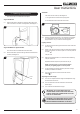
User Instructions 2. Operating the Appliance All Models The valve has two controls, see Diagram 3. The control valve is located behind the plinth. 1. The right-hand knob controls the pilot ignition. Vogue Midi Models 2.1 Remove the plinth to access the controls by lifting the hooks clear of the slots on the front of the appliance, see Diagram 1. 2. The left-hand knob controls the main burner. 3 1 2.3 Refer to separate instructions if your appliance is upgraded to include battery remote control.
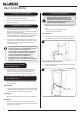
User Instructions 3. Turning OFF the Appliance 3.1 To turn the main burner off turn the left-hand knob until it points to off ( ). Just the pilot remains lit. 3.2 Press in and turn the right-hand knob until it points to off ( ). The pilot goes out. 4. Upgrading the Appliance 4.1 4.2 The appliance is fitted with a control valve that can easily be upgraded to battery powered remote control. There are two versions of this control which can be obtained through your local Gazco retailer.
User Instructions All Models 5.4 Remove the frame to gain access to the viewing aperture by lifting the hooks clear of the slots on the front of the appliance, see Diagram 6. 5.6 The frame can be removed by lifting the hooks clear of the slots from the bottom of the frame and lifting away from the appliance, see Diagram 9. 9 Vogue Midi Shown 5.7 The glass frame must be refitted to the appliance following cleaning or servicing. Hold in position and secure with the screws. 5.
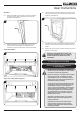
User Instructions 7. Log Layout LOGS MUST BE POSITIONED ACCORDING TO THE FOLLOWING INSTRUCTIONS TO GIVE THE CORRECT FLAME EFFECT. 7.4 Position the 2 embers on the lip at the front of the fuel bed, see Diagram 13. 13 Midi/ Midi Midline Nat Gas Burner shown All logs can be identified by a letter (A - D) on their underside. Logs A and B have holes to locate each onto a burner stud. 7.1 Ensure the burner tray is clean and free from any debris, see Diagram 10.
User Instructions 7.7 Log D fits onto the locating pin and rests on Log B, see Diagram 16. 10.1 16 During initial use of a new Gazco appliance a strong odour will be encountered as various surface coatings become hot for the first time. Although these odours are harmless it is recommended that the appliance is operated on maximum for 4 to 8 hours in order to fully burn off these coatings. After this period the odours should then disappear.
Installation Instructions Technical Specification Covering the following models: Model VOGUE MIDI VOGUE MIDI T MIDI VOGUE MIDI MIDLINE VOGUE MIDI T MIDLINE VOGUE MIDI T HIGHLINE Nat Gas 563-123 563-180 563-392 563-224 563-191 LPG 563-426 563-701 563-466 563-493 563-447 Model Vogue Midi / Vogue Midi Midline Vogue Midi T - Midi / Vogue Midi T - Midline / Vogue Midi T - Highline Gas CAT. Gas Type Working Pressure Aeration Injector Gas Rate m3/h I2H Natural Gas (G20) 20mbar 2 x 5.
Installation Instructions Technical Specification PACKING CHECKLIST This appliance has been certified for use in countries other than those stated. To install this appliance in these countries, it is essential to obtain the translated instructions and in some cases the appliance will require modification. Contact Gazco for further information.
Installation Instructions Technical Specification Vogue Midi Midline B G D E A C F Vogue Midi T - Midi B G D E H C A F Model 12 A B C D E F G H Vogue Midi Midline 791 416 367 208 121 630 11 - Vogue Midi T - Midi 776 416 348 208 121 615 11 367
Installation Instructions Technical Specification B Vogue Midi T - Midline G D E H A C F B Vogue Midi T - Highline G D E H A C F Model A B C D E F G H Vogue Midi T - Midline 928 416 348 208 121 767 11 367 Vogue Midi T - Highline 1260 416 348 208 121 1099 11 367 13
Installation Instructions Site Requirements 1. Flue & Chimney Requirements 1.1 The chimney or flue system must comply with the rules in force, and must be a minimum of 127mm in diameter. (5"). 1.2 The minimum flue height for the appliance must be 3 metres (10ft). Any horizontal flue run from the rear outlet must not exceed 100mm from the back of the appliance. 1.3 The chimney or flue must be free from any obstruction.
Installation Instructions Site Requirements 5.4 5.5 5.6 The non-combustible hearth must be at least 12mm thick, and project a minimum of 50mm from the base of the appliance in all directions. The appliance is not suitable for installation against a combustible wall. A combustible side wall must be a minimum of 150mm (Vogue Midi / Midi Midline) or 200mm (Vogue Midi T Midi/ Midi T Midline / Midi T Highline) from the appliance. MINIMUM CLEARANCE 5.
Installation Instructions 1. Safety Precautions 1.1 For your own and other’s safety, you must install this appliance according to local and national codes of practice. Failure to install the appliance correctly could lead to prosecution. Read these instructions before installing and using this appliance. 1.2 These instructions must be left intact with the user. 1.3 Do not attempt to burn rubbish on this appliance. 1.4 Keep all plastic bags away from young children. 1.
Installation Instructions 3. Installation of the Appliance IMPORTANT: THE OUTER PANELLING OF THE VOGUE MIDI IS MADE FROM CAST IRON. USE CAUTION WHEN INSTALLING, REMOVING AND STORING AS THE COMPONENTS ARE HEAVY AND SHOULD BE HANDLED CAREFULLY. All Models 3.3 Remove the frame to gain complete access to the control valve and the viewing aperture by lifting the hooks clear of the slots on the front of the appliance, see Diagram 3. 3 Vogue Midi Models 3.
Installation Instructions 3.7 Lift the appliance so as to locate the key slots in the carcass onto the fixing screws. There are two large holes the lower flanges on the front edges of the base, see Diagram 5. 5 4. Top or Rear Exit 4.1 Before locating the appliance choose the correct flue outlet position. 4.2 The appliance is supplied as a top exit configuration. To switch outlets remove the cast top plate, see Diagram 7. 7 Key slots 3.
Installation Instructions 4.5 Swap the flue spigot only with the Blanking Plate on the rear of the appliance, see Diagram 10. 10 4.8 Replace the cast top. When fitted properly the cast plate should sit flush with the rear of the stove, see Diagram 13. 13 Vogue Midi Shown Blanking Plate 4.6 Attach the decorative flue blanking plate support bracket to the underside of the cast top using the screws provided. Ensure the folded return is pressed against the cast top, see Diagram 11. 11 5.
Installation Instructions 7. Arrangement of Fuel Bed 6. Removing the Glass 6.1 Using a screwdriver remove the 4 screws securing the window panel to the appliance, see Diagrams 16 & 17. Take care to support the glass when removing the screws. Advice on handling and disposal of fire ceramics Vogue Midi & Midline The fuel effect in this appliance are made from Refractory Ceramic Fibre (RCF), a material which is commonly used for this application.
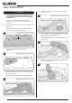
Installation Instructions 8.2 Place Log A in position on the 2 locating pins, see Diagram 20. 20 8.5 Log B is positioned on the right hand locating pin, and rests against the back liner, see Diagram 23. Midi/ Midi Midline Nat Gas only: Log B also rests on the rear burner bracket. Midi/ Midi Midline Nat Gas Burner shown 23 B A 8.3 Spread the Lava Rock evenly over the fuel bed and around Log A, see Diagram 21. Ensure that the fuel effect does not obstruct the pilot.
Installation Instructions 8.8 Sparingly spread an amount of the Embaglow fibres provided on the sections highlighted, see Diagram 26. Take care not to use more than half a packet per application. 29 WARNING - DO NOT PLACE NEAR THE PILOT AREA. 26 9. Completion of Assembly 9.1 To fit the window frame: Offer the top of the frame to the opening and lower to engage hooks. 27 UNDER NO CIRCUMSTANCES SHOULD THE APPLIANCE BE USED IF ANY OF THE GLASS FRAME RETAINING SCREWS ARE LOOSE OR MISSING. All Models 9.
Installation Instructions 9.5 Push the lower door closed, see Diagram 32. 32 Vogue Midi Midline Shown The control valve is located behind the lower door. 10.2 Pull the lower door open from the right hand side to access the controls, see Diagram 34. 34 Vogue Midi Midline Shown Control Valve 10. Operating the Appliance The method used to access the control valve differs between models. All Models The valve has two controls, see Diagram 35. Vogue Midi Models 1.
Installation Instructions/Commissioning The pilot remains lit. 1. Commissioning Repeat the above steps if the pilot does not stay lit. NOTE: If the pilot goes out, the Interlock system prevents you lighting again for a short period. 10.7 If, after repeating the above steps the pilot does not light, contact your Retailer or Installer. 10.8 Turn the right-hand knob to the left to main burner setting ( ). Adjusting the Flame height 10.
Servicing Instructions Servicing/Fault Finding Charts 1.2 1. Servicing Requirements IMPORTANT – The glass panel on this appliance should be checked for any signs of damage on the front face of the glass panel (scratches, scores, cracks or other surface defects). If damage is observed, the glass panel must be replaced and the appliance must not be used until a replacement is installed. Under no circumstances should the appliance be used if any damage is observed.
Replace the combined lead and piezo, retry. No Is the electrode wire detached from the piezo in the valve? No Replace the electrode. Yes Yes No No Yes Yes Replace the piezo and gas valve and retry. No Remove the electrode lead from the piezo. Operate the valve. Does a spark jump from the piezo to the valve body? Check for defective or damaged control knob spindle or cam operation. Check for correct location of piezo components. Correct and retry. Correct and retry.
Servicing Instructions - Replacing Parts All Models 1. General 1.1 All main components can be replaced without removing the appliance from its installation. IT IS ESSENTIAL THAT THE GAS SUPPLY TO THE APPLIANCE IS TURNED OFF AT THE ISOLATION DEVICE BEFORE PROCEEDING FURTHER. 2.3 Remove the frame to gain complete access to the control valve and the viewing aperture by lifting the hooks clear of the slots on the front of the appliance, see Diagram 3. 3 Vogue Midi Shown 2.
Servicing Instructions - Replacing Parts 3.2 The frame can be removed by lifting the hooks clear of the slots from the bottom of the frame and lifting away from the appliance, see Diagram 6. 6 Vogue Midi Shown BLACK GLASS LINERS Once the baffle has been removed the liners can then be taken out. 4.3 To remove the side liners: Tilt towards the centre of the firebox. Lift up and pull out of position, see Diagram 8. 8 3.3 Place carefully to one side. 3.
Servicing Instructions - Replacing Parts 4.5 With the liners and baffle removed the firebox is clear for cleaning and maintenance, see Diagram 10. 10 REAR PANEL & TRIMS 4.9 The rear panel is in one piece. Undo the 2 screws and lean forward to remove. 13 14 4.6 To replace the liners and baffle reverse these procedures. 4b. Vogue Midi T Midi, Midline & Highline BAFFLE 4.7 The baffle consists of two parts, the Main Baffle and the Rear Baffle.
Servicing Instructions - Replacing Parts 4.11 To remove the side trim lift and hook off the firebox, see Diagram 16. NOTE: The Side Trims only need to be removed if damaged or the side glass needs replacing. 5.4 Lift the burner out of the firebox at an angle clear the brackets, exposing the service hatch, see Diagram 19. 19 Service Hatch Screws 16 5.5 Refit in reverse order. Important: Ensure the burner engages with the injector at the base of the firebox, see Diagram 20. 20 Injector 5.
Servicing Instructions - Replacing Parts 6.4 Reposition the service hatch and tighten the 4 screws, see Diagram 22. 7a. Pilot Burner Bracket 22 To remove the Pilot Burner Bracket: 7.2 First remove the electrode, pilot pipe and thermocouple as described in the following sections. 7.3 Remove the 2 screws securing the bracket. The pilot burner bracket can now be removed. 7.4 Replace in reverse order. 7b. Electrode This side face down 7.
Servicing Instructions - Replacing Parts 10. Gas Valve 8. Ignition Lead 8.1 Follow the Pilot Unit instruction to access the back of the pilot assembly. 10.1 To remove the valve turn off the gas supply at the isolation device. 8.2 Disconnect the ignition lead from the electrode. 10.2 Remove the main burner, see Section 5. 8.3 Remove the front cover from the control valve by removing the retaining screw, see Diagram 24 and gently levering clear with flat bladed screwdriver, see Diagram 25. 10.
Servicing Instructions - Replacing Parts 10.8 Disconnect the 2 x 8mm and 1 x 4mm gas pipe fittings at the back of the gas valve, see Diagram 28 (A). 10.9 Disconnect the thermocouple, see Diagram 28 (B). 28 C 12. Main Injector 12.1 To remove the main injector turn off the gas supply at the isolation device. 12.2 Remove the main burner, see Section 5. 12.3 Undo the compression nuts from the feed pipe and the gas valve under the appliance. 12.
Servicing Instructions - Replacing Parts 13.2 Undo the 3 screws securing the rear bracket and remove, see Diagram 32. 15. Primary Aeration Plate 32 13.3 NOTE: Not all models have aeration plates. Please refer to the Technical Specification. Replace the glass and gasket, ensuring that the printed side is facing outwards. 15.1 To replace the primary aeration plate turn off the gas supply at the isolation device. 15.2 Remove the burner, see Installation Instructions, Replacing Parts, Section 5. 15.
Servicing Instructions - Replacing Parts 18. Spares List - Vogue Midi No. Component Part Code Natural Gas LPG Quantity No.
Servicing Instructions - Replacing Parts 18. Spares List - Vogue Midi T Midi No. Component Part Code Quantity No.
Servicing Instructions - Replacing Parts 18. Spares List - Vogue Midi Midline No. Component Part Code Natural Gas LPG Quantity No.
Servicing Instructions - Replacing Parts 18. Spares List - Vogue Midi T Midline No. Component Part Code Natural Gas LPG Quantity No.
Servicing Instructions - Replacing Parts 18. Spares List - Vogue Midi T Highline No. Component Part Code Natural Gas LPG Quantity No.
Servicing Instructions - Replacing Parts 18. Spares List - Control Assembly No.
Service Records 1ST SERVICE 2ND SERVICE Date of Service........................................................................... Date of Service......................................................................... Next Service Due....................................................................... Next Service Due..................................................................... Signed........................................................................................ Signed..........
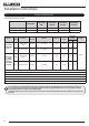
Information Requirement - Gas Heaters Vogue Midi CF NG Vogue Midi CF LPG Vogue Midi Midline CF NG Vogue Midi Midline CF LPG Vogue Midi T Midi CF NG 130 130 130 130 130 Nominal Heat Output - Pnom 4.2kW 4.3kW 4.2kW 4.3kW 4.2kW Minimum Heat Output (indicative) - Pmin 1.6kW 1.6kW 1.6kW 1.6kW 2.
Information Requirement - Gas Heaters Vogue Midi T Midline CF LPG 130 130 130 Nominal Heat Output - Pnom 4.1kW 4.2kW 4.1kW 4.2kW 4.1kW Minimum Heat Output (indicative) - Pmin 2.0kW 2.1kW 2.0kW 2.1kW 2.0kW Auxiliary Electricity Consumption At Nominal Heat Output - elmax N/A N/A N/A N/A N/A At Minimum Heat Output - elmin N/A N/A N/A N/A N/A In Standby Mode - elsb N/A N/A N/A N/A N/A Useful Efficiency at nominal heat output - ηth,nom 78.0% 78.0% 78.0% 78.0% 78.
Gazco Limited, Osprey Road, Sowton Industrial Estate, Exeter, Devon, England EX2 7JG Technical Customer Services: (01392) 261950 Fax: (01392) 261951 E-mail: technicalservices@gazco.