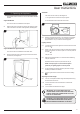
Vogue Range Balanced Flue Log Effect Stove With Upgradeable Control Valve Instructions for Use, Installation and Servicing For use in GB, IE (Great Britain and Republic of Ireland) IMPORTANT THE OUTER CASING, FRONT AND GLASS PANEL BECOME EXTREMELY HOT DURING OPERATION AND WILL RESULT IN SERIOUS INJURY AND BURNS IF TOUCHED. IT IS THEREFORE RECOMMENDED THAT A FIREGUARD COMPLYING WITH BS 8423 (LATEST EDITION) IS USED IN THE PRESENCE OF YOUNG CHILDREN, THE ELDERLY OR INFIRM.
Contents Vogue Freestanding - Balanced Flue Covering the following models: MODEL VOGUE MIDI VOGUE MIDI T 3 SIDED VOGUE MIDI MIDLINE VOGUE MIDI T MIDLINE 3 SIDED VOGUE MIDI T WALL MOUNTED 3 SIDED VOGUE MIDI T HIGHLINE 3 SIDED Nat Gas 563-016 563-025 563-258 563-300 563-013 563-216 LPG 563-400 563-749 563-790 563-676 563-506 563-458 Appliance Commissioning Checklist.......................3 User Instructions........................................................
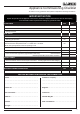
Appliance Commissioning Checklist To assist us in any guarantee claim please complete the following information:- IMPORTANT NOTICE Explain the operation of the appliance to the end user, hand the completed instructions to them for safe keeping, as the information will be required when making any guaranteed claims. FLUE CHECK PASS FAIL 1. Flue Is correct for appliance 2. Flue flow Test N/A 3. Spillage Test N/A GAS CHECK 1. Gas soundness & let by test 2. Standing gas pressure mb 3.
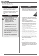
User Instructions 1. General Welcome Congratulations on purchasing your Gazco Vogue, if installed correctly Gazco hope it will give you many years of warmth and pleasure for which it was designed. 1.1 Installation and servicing must only be carried out by a competent person whose name appears on the GasSafe register. To ensure the engineer is registered with GasSafe they should possess an ID Card carrying the following logo: 1.
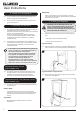
User Instructions 2. Operating the Appliance All Models The valve has two controls, see Diagram 3: The method used to access the control valve differs between models. 1. The right-hand knob controls the pilot ignition. 2. The left-hand knob controls the main burner. Vogue Midi Models The control valve is located behind the plinth. 2.1 3 Remove the plinth to access the controls by lifting the hooks clear of the slots on the front of the appliance, see Diagram 1. 1 2.
User Instructions 3. Turning OFF the Appliance 3.1 To turn the main burner off turn the left-hand knob until it points to off ( ). Just the pilot remains lit. 3.2 Press in and turn the right-hand knob until it points to off ( ). The pilot goes out. TIMER MODE Will turn the appliance on and off according to a pre-set programme and automatically regulate the room temperature during the two on periods. 5. Cleaning the Appliance IMPORTANT: THE OUTER PANELLING OF THE GAZCO VOGUE IS MADE FROM CAST IRON.
User Instructions All Models 5.4 Remove the frame to gain access to the viewing aperture by lifting the hooks clear of the slots on the front of the appliance, see Diagram 6. 5.6 The frame can be removed by lifting the hooks clear of the slots from the bottom of the frame and lifting away from the appliance, see Diagram 9. 9 Vogue Midi Shown 5.7 The glass frame must be refitted to the appliance following cleaning or servicing. Hold in position and secure with the screws. 5.
User Instructions 7. Log Layout LOGS MUST BE POSITIONED ACCORDING TO THE FOLLOWING INSTRUCTIONS TO GIVE THE CORRECT FLAME EFFECT. 7.4 Position the 2 embers on the lip at the front of the fuel bed, see Diagram 13. 13 All logs can be identified by a letter (A - D) on their underside. Logs A and B have holes to locate each onto a burner stud. 7.1 Ensure the burner tray is clean and free from any debris, see Diagram 10. 10 7.
User Instructions 7.7 Log D fits onto the locating pin and rests on Log B, see Diagram 16. 10. Servicing 10.1 16 D The appliance must be serviced every 12 months by a qualified GasSafe Engineer. In all correspondence always quote the Model number and the Serial number which may be found on the Commissioning Checklist (Page 3). 11. Ventilation 11.1 This appliance requires no additional ventilation. 12. Installation Details 12.1 7.
Installation Instructions Technical Specification Covering the following models: MODEL VOGUE MIDI VOGUE MIDI T 3 SIDED VOGUE MIDI MIDLINE VOGUE MIDI T MIDLINE 3 SIDED VOGUE MIDI T WALL MOUNTED 3 SIDED VOGUE MIDI T HIGHLINE 3 SIDED Nat Gas 563-016 563-025 563-258 563-300 563-013 563-216 LPG 563-400 563-749 563-790 563-676 563-506 563-458 Model Vogue Midi / Vogue Midi Midline Vogue Midi T 3 Sided / Vogue Midi T Wall Mounted 3 Sided / Vogue Midi T Midline 3 Sided / Vogue Midi T Highline
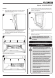
Installation Instructions Technical Specification Vogue Midi B G D E C A F Vogue Midi Midline B G D E A C F Model A B C D E F G Vogue Midi 639 416 348 208 137 470 11 Vogue Midi Midline 791 416 348 208 137 622 11 11
Installation Instructions Technical Specification Vogue Midi T 3 Sided B G D E C A F B Vogue Midi T Midline 3 Sided G D E A C F Model 12 A B C D E F G Vogue Midi T 3 Sided 776 416 348 209 137 607 11 Vogue Midi T Midline 3 Sided 928 416 348 209 137 759 11
Installation Instructions Technical Specification B Vogue Midi T Highline 3 Sided F E D A G C Model Vogue Midi T Highline 3 Sided A B C D E F G 1260 416 348 137 209 11 1091 Vogue Midi T 3 Sided - Wall Mounted B G E F D C A Model Vogue Midi T 3 Sided - Wall Mounted A B C D E F G 776 416 348 360 209 137 11 13
Installation Instructions Technical Specification This appliance has been certified for use in countries other than those stated. To install this appliance in these countries, it is essential to obtain the translated instructions and in some cases the appliance will require modification. Contact Gazco for further information.
Installation Instructions Site Requirements 1. Flue and Chimney Requirements Note: This appliance must only be installed with the flue supplied. You must adhere to the following: 1.1 The flue must be sited in accordance with BS5440: Part 1 (latest edition), see Diagram 1. 1.2 Fit a guard to protect people from any terminal less than 2 metres above any access such as level ground, a balcony or above a flat roof. 1.
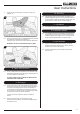
Installation Instructions Site Requirements 3. Rear Flue 3.1 3B Vogue Midi T/ Midline/ Highline This flue extends horizontally from the back of the appliance, see Diagram 2. ALL MODELS (8526) 2 200mm min 550mm max Terminal dimensions: 395 x 200 x 200 mm (H x W x D) Guard supplied Cut to length as required on site, see Diagram 2. There are two types of flue terminal: horizontal (Section 3b) and vertical (Section 3d). 3a. Top Flue Up and Out Kit 3.
Installation Instructions Site Requirements 8524/8524AN - Vogue Midi/ Midline/ Highline T Models 3c. Top Flue Up and Out with Additional Bend 3.12 The basic kit comprises: 2 x 1m lengths 1 x 1m terminal length 1 x 52mm restrictor 1 x 47mm restrictor - Not used on this appliance 1 x 60mm restrictor 1 x 70mm restrictor - Not used on this appliance An additional bend can be used on the horizontal section (45° or 90°) but the overall horizontal flue is reduced, see Diagram 4.
Installation Instructions Site Requirements 4. Optional Extra Flue Lengths and Bends Nominal Length Actual Length Stainless Finish Anthracite Finish 200mm 140mm 8527 8527AN 500mm 440mm 8528 8528AN 1000mm 940mm 8529 8529AN 45° Bend N/A 8507 8507AN 90° Bend N/A 8508 8508AN Optional Flue Collar 7.2 To Install the Bench: Follow Section 1 Installation - All Models in Installation guide PM205 supplied with the bench kit. 7.
Installation Instructions Site Requirements NOTE: It is not recommended to install Midline/ Highline models on a bench. MIDLINE & HIGHLINE MODELS 7.8 7.9 It is not necessary to site these products on a noncombustible floor. However, for practical reasons, the floor should be flat and solid to allow the appliance to be levelled and secured in place. MINIMUM CLEARANCE 7.12 Freestanding appliances are not suitable for installation against a combustible wall. (NOT APPLICABLE FOR WALL MOUNTED MODELS.) 7.
Installation Instructions 1. Safety Precautions 1.1 For your own and other’s safety, you must install this appliance according to local and national codes of practice. Failure to install the appliance correctly could lead to prosecution. Read these instructions before installing and using this appliance. 1.2 These instructions must be left intact with the user. 1.3 Do not attempt to burn rubbish on this appliance. 1.4 Keep all plastic bags away from young children. 1.
Installation Instructions 3. Installation of the Appliance IMPORTANT: THE OUTER PANELLING OF THE VOGUE MIDI IS MADE FROM CAST IRON. USE CAUTION WHEN INSTALLING, REMOVING AND STORING AS THE COMPONENTS ARE HEAVY AND SHOULD BE HANDLED CAREFULLY. All Models 3.3 Remove the frame to gain complete access to the control valve and the viewing aperture by lifting the hooks clear of the slots on the front of the appliance, see Diagram 3. 3 Vogue Midi Models 3.
Installation Instructions 3.7 Lift the appliance so as to locate the key slots in the carcass onto the fixing screws. There are two large holes the lower flanges on the front edges of the base, see Diagram 5. 5 Key slots 3.8 Securing the Appliance to the Wall Vogue Midi T 3 Sided Wall Mounted only 3.13 To install the Vogue as a wall mounted product it will be necessary to remove the rear vanity panel. 3.14 Remove the 4 screws, see Diagram 7, Arrow A. 3.
Installation Instructions 3.17 Tighten the 4 loose screws (Diagram 7, Arrow B) and replace the top 2 screws (Diagram 7, Arrow A). 3.21 WARNING: This appliance weighs 62kg. The manufacturer has designed this appliance to attach to a masonry wall and all fixings supplied reflect this. If siting on a studwork wall, the fixing points must be through the timber stud and not plasterboard. Use appropriate fixings. DO NOT attach solely to a plasterboard wall.
Installation Instructions NOTE: The top rear edge of the appliance must locate between the back lip of the wall mounting bracket and the raised supports, see Diagram 12. 12 Partially Engaged 4.3 The cast top plate lifts off to give access to the inner and outer flue spigots, see Diagram 14. 14 Stove Body Wall Mounting Bracket Fully Engaged Stove Body Back Lip Raised Support 4.4 Wall Mounting Bracket 3.28 Remove the 8 screws securing the inner & outer spigots, see Diagram 15.
Installation Instructions 4.6 Attach the decorative flue blanking plate support bracket to the underside of the cast top using the screws provided. Ensure the folded return is pressed against the cast top, see Diagram 17. 5. Highline Freestanding Back Panel (Optional) The Vogue Highline can be supplied with an optional back panel to allow the appliance to be installed in a manner where it can be viewed from 360° without viewing the engine components. Consult your Gazco retailer for details.
Installation Instructions 5.5 Take care when fitting the back panel not to catch the gas inlet extension pipe. This will protrude from the cutout at the bottom of the panel, see Diagram 23. 23 6.10 The Wall Mounted Kit is supplied with a protective sleeve for the flue. This can be rolled to fit through the hole in the internal wall. 6.11 Feed the sleeve through the hole in the internal wall. This will expand in the cavity to protect the flue from debris etc. 6.12 Fit the flue as detailed, see 6.13.
Installation Instructions 6.25 Any terminal less than 2m above any access (level ground, balcony or flat roof with access) must be fitted with the guard supplied, see Diagram 26. 26 6.29 TAKE CARE TO MARK OUT THE FLUE CORRECTLY. IT IS DIFFICULT TO MOVE AFTER INSTALLATION. 6.30 Create a 152mm (6”) diameter hole for the flue using either: a) a core drill, or b) a hammer and chisel 6.31 Make good at both ends of the hole. Flue Length 6.32 The final length of the flue pipe includes the terminal.
Installation Instructions Flue and Appliance Fixings 6.40 Pull appliance and flue assembly away from the hearth. 6.41 Drill 4 fixing holes for the wall plate and insert wall plugs supplied. 6.42 Put the horizontal flue onto the elbow and reposition the appliance. 6.43 Check the flue runs smoothly through the wall. 6.44 Fix the wall plate to the wall using the 4 black screws provided. 6.45 Drill through the fixing tab of the wall plate using a 3.5mm drill. 6.46 Secure with the screw provided.
Installation Instructions Vogue Midi, Midline & Highline T 3 Sided 9. Arrangement of the Fuel Bed 34 Advice on handling and disposal of fire ceramics The fuel effect of the log version of this appliance is made from Refractory Ceramic Fibre (RCF), a material which is commonly used for this application.
Installation Instructions 9.2 Place Log A in position on the 2 locating pins, see Diagram 37. 37 9.6 41 C A 9.3 Log C rests on Log A and the front tray with the locating pin facing up, see Diagram 41. Spread the Lava Rock evenly over the fuel bed and around Log A, see Diagram 38. 38 9.7 Log D fits onto the locating pin and rests on Log B, see Diagram 42. 42 D 9.4 Position the 2 embers on the lip at the front of the fuel bed, see Diagram 39. 9.
Installation Instructions 10. Completion of Assembly 10.1 To fit the window frame: Offer the top of the frame to the opening and lower to engage hooks. 44 All Models 10.3 Fit the front by inserting the hooks on the back of the frame into the slots on the front of the appliance, see Diagram 47. 47 Vogue Midi Shown Vogue Midi 10.4 10.2 Replace ALL of the glass frame securing screws ensuring that a screw is present in all fixing slots, see Diagram 45 & 46.
Installation Instructions 11. Operating the Appliance All Models The valve has two controls, see Diagram 50: The method used to access the control valve differs between models. 1. The right-hand knob controls the pilot ignition. 2. The left-hand knob controls the main burner. Vogue Midi Models The control valve is located behind the plinth. 11.1 52 Remove the plinth to access the controls by lifting the hooks clear of the slots on the front of the appliance, see Diagram 50. 50 11.
Commissioning 1. Commissioning the Appliance 1.1 Complete the Commissioning Checklist at the front of this manual covering: — Thermocouple soundness checks. This is to include ensuring the thermocouple is secure on the pilot bracket assembly, lead connection and integrity. — Flue checks — Gas checks — Log/fuel effect layout - flame picture 1.
Servicing Instructions Servicing/Fault Finding Charts 1.2 1. Servicing Requirements IMPORTANT – The glass panel on this appliance should be checked for any signs of damage on the front face of the glass panel (scratches, scores, cracks or other surface defects). If damage is observed, the glass panel must be replaced and the appliance must not be used until a replacement is installed. Under no circumstances should the appliance be used if any damage is observed.
Replace the combined lead and piezo, retry. No Is the electrode wire detached from the piezo in the valve? No Replace the electrode. Yes Yes No No Yes Yes Replace the piezo and gas valve and retry. No Remove the electrode lead from the piezo. Operate the valve. Does a spark jump from the piezo to the valve body? Check for defective or damaged control knob spindle or cam operation. Check for correct location of piezo components. Correct and retry. Correct and retry. Reset the pilot burner.
Servicing Instructions - Replacing Parts All Models 1. General 1.1 All main components can be replaced without removing the appliance from its installation. IT IS ESSENTIAL THAT THE GAS SUPPLY TO THE APPLIANCE IS TURNED OFF AT THE ISOLATION DEVICE BEFORE PROCEEDING FURTHER. 1.2 2.3 Remove the frame to gain complete access to the control valve and the viewing aperture by lifting the hooks clear of the slots on the front of the appliance, see Diagram 3.
Servicing Instructions - Replacing Parts 3.2 The frame can be removed by lifting the hooks clear of the slots from the bottom of the frame and lifting away from the appliance, see Diagram 6. 6 Vogue Midi Shown BLACK GLASS LINERS Once the baffle has been removed the liners can then be taken out. 4.3 To remove the side liners: Tilt towards the centre of the firebox. Lift up and pull out of position, see Diagram 8. 8 3.3 Place carefully to one side. 3.
Servicing Instructions - Replacing Parts 4.5 With the liners and baffle removed the firebox is clear for cleaning and maintenance, see Diagram 10. 10 4.8 To remove the Rear baffle, undo the 2 screws, see Diagram 13. 13 Note: When replacing the Rear Baffle ensure that the tab locates behind the rear panel slot, see Diagram 14. 14 4.6 To replace the liners and baffle reverse these procedures. Rear Baffle 4b. Vogue 3 Sided Midi & Midline BAFFLE 4.
Servicing Instructions - Replacing Parts 4.10 To remove the fuel bed trim undo the 2 screws and slide out of the locating slot in the side trims, see Diagram 16, Detail A. 16 5. Main Burner To replace the main burner: 5.1 Remove the 2 securing screws at the front of the burner, see Diagram 18. 18 Detail A 3 Sided Models Only: 4.11 To remove the side trim lift and hook off the firebox, see Diagram 17. NOTE: The Side Trims only need to be removed if damaged or the side glass needs replacing. 5.
Servicing Instructions - Replacing Parts 6. Control Assembly & Service Hatch 6.1 6.2 7. Pilot Unit It is not necessary to remove the complete control assembly to service or replace parts of this appliance. The following sections will detail how to individually remove and replace each element. The pilot assembly consists of 4 components which can be individually changed: 7a) Pilot burner bracket. 7b) Electrode. 7c) Pilot injector. 7d) Thermocouple.
Servicing Instructions - Replacing Parts 7c. Pilot Injector 7.8 Undo the pilot pipe from the gas valve and from the underside of the pilot burner, see Diagram 23. 7.9 Remove the pipe and the injector drops out from the burner. 7d. Thermocouple 8.4 Disconnect the other end of the ignition lead from the valve body noting the route of the ignition lead. 8.5 Replace with a new ignition lead following the same route as the old one. Replace the valve cover and the pilot assembly. 8.
Servicing Instructions - Replacing Parts Vogue Midi & Midline T 3 Sided 11. Magnetic Safety Valve 27 Screws 10.7 Slide the bracket slightly to the right and pull forward to access the valve connections. 10.8 Disconnect the 2 x 8mm and 1 x 4mm gas pipe fittings at the back of the gas valve, see Diagram 28 (A). 10.9 Disconnect the thermocouple, see Diagram 28 (B). 11.1 Turn the gas supply off at the isolation device. 11.2 Remove the gas valve, see Section 10. 11.
Servicing Instructions - Replacing Parts 13. Glass Side Panels 3 Sided Models Only To service the glass side panels, first remove the back panel and the side trims (see Section 4b). 13.1 Undo the four screws securing the front bracket and remove, see Diagram 31. 31 14. Primary Aeration Plate NOTE: Not all models have aeration plates. Please refer to the Technical Specification. 14.1 To replace the primary aeration plate turn off the gas supply at the isolation device. 14.
Servicing Instructions - Replacing Parts 17. Explosion Relief Gasket IMPORTANT: If it is required to access the rear explosion relief for servicing the appliance must first be removed from the wall. 17.1 It is possible to change the gasket on the explosion relief panel. Rear Explosion Relief 17.2 Remove the 6 screws on each spring panel and the 4 from the centre bracket. 34 17.3 Rear of Appliance Rear Explosion Relief Remove the gasket and replace.
Servicing Instructions - Replacing Parts 18. Spares List - Control Assembly No.
Servicing Instructions - Replacing Parts 18. Spares List - Vogue Midi No. Component Part Code Natural Gas LPG Quantity No.
Servicing Instructions - Replacing Parts 18. Spares List - Vogue Midi Midline No. Component Part Code Natural Gas LPG Quantity No.
Servicing Instructions - Replacing Parts 18. Spares List - Vogue Midi T Midline 3 Sided Due to continual technical improvements please check online or with your Gazco retailer for the most up to date parts lists. Only use Genuine Gazco spares when servicing your appliance. All of our essential spare parts and consumable items are available to purchase from our webshop at www.gazcospares.com.
Servicing Instructions - Replacing Parts 18. Spares List - Vogue Midi T Midline 3 Sided No. Component Part Code No.
Servicing Instructions - Replacing Parts 18. Spares List - Vogue Midi T 3 Sided Due to continual technical improvements please check online or with your Gazco retailer for the most up to date parts lists. Only use Genuine Gazco spares when servicing your appliance. All of our essential spare parts and consumable items are available to purchase from our webshop at www.gazcospares.com.
Servicing Instructions - Replacing Parts 18. Spares List - Vogue Midi T 3 Sided No. Component 1 Outer Spigot 2 Outer Spigot Gasket 3 Inner Spigot 4 Part Code Quantity No.
Servicing Instructions - Replacing Parts 18. Spares List - Vogue Midi T 3 Sided Wall Mounted Due to continual technical improvements please check online or with your Gazco retailer for the most up to date parts lists. Only use Genuine Gazco spares when servicing your appliance. All of our essential spare parts and consumable items are available to purchase from our webshop at www.gazcospares.com.
Servicing Instructions - Replacing Parts 18. Spares List - Vogue Midi T 3 Sided Wall Mounted No. Component Part Code No.
Servicing Instructions - Replacing Parts 18. Spares List - Vogue Midi T Highline 3 Sided Due to continual technical improvements please check online or with your Gazco retailer for the most up to date parts lists. Only use Genuine Gazco spares when servicing your appliance. All of our essential spare parts and consumable items are available to purchase from our webshop at www.gazcospares.com.
Servicing Instructions - Replacing Parts 18. Spares List - Vogue Midi T Highline 3 Sided No. Component Part Code No.
Service Records 56 1ST SERVICE 2ND SERVICE Date of Service........................................................................... Date of Service......................................................................... Next Service Due....................................................................... Next Service Due..................................................................... Signed........................................................................................ Signed.....
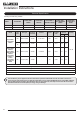
Information Requirement - Gas Heaters Vogue Midi BF NG Vogue Midi BF LPG Vogue Midi Midline BF NG Vogue Midi Midline BF LPG Vogue Midi T 3 Sided BF NG Vogue Midi T 3 Sided BF LPG Information Requirement for Gaseous Fuel Local Space Heater 130 130 130 130 130 130 Nominal Heat Output - Pnom 3.9kW 4.0kW 3.9kW 4.0kW 4.8kW 4.3kW Minimum Heat Output (indicative) -Pmin 1.8kW 1.8kW 1.8kW 1.8kW 2.9kW 2.
Information Requirement - Gas Heaters Pilot Flame Power requirement Useful Efficiency Auxiliary Electricity Consumption Heat Output Fuel Space Heating Emissions (NOx) - mg / kWh input (GCV) Vogue Midi T Highline 3 Sided BF LPG Vogue Midi T Highline 3 Sided BF NG Vogue Midi T Wall Mounted 3 Sided BF LPG Vogue Midi T Wall Mounted 3 Sided BF NG Model Vogue Midi T Midline 3 Sided BF LPG Vogue Midi T Midline 3 Sided BF NG Information Requirement for Gaseous Fuel Local Space Heater 130 130 130 1
Gazco Limited, Osprey Road, Sowton Industrial Estate, Exeter, Devon, England EX2 7JG Technical Customer Services: (01392) 261950 Fax: (01392) 261951 E-mail: technicalservices@gazco.