
Logic HE Conventional Flue Combined Controls Installation User Instructions

37
Servicing Instructions - Replacing Parts
All Models
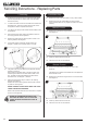
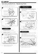
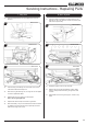
5.13 Replace with a new pilot assembly and check the spark gap,
see Diagram 24.
24
5.14 After reassembly check for gas soundness and carry out
a flame failure functional check as detailed in the Fault
Finding chart, especially the time it takes for the mag unit to
close.
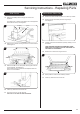
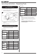
6. Gas Valve
Manual Control
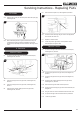
6.1 To remove the gas valve first remove the thermocouple,
see Diagram 25, Arrow A.
C
B
A
25
D
6.2 Undo the pilot pipe from the gas valve, see Diagram 25,
Arrow B.
6.3 Undo the inlet pipe from the gas valve, see Diagram 25,
Arrow C.
6.4 Undo the main injector feed pipe from the gas valve,
see Diagram 25, Arrow D.
6.5 Disconnect the injector nut, see Diagram 26, Arrow E.
E
26
6.6 Undo the 2 bolts securing the gas valve to the appliance
and remove the valve unit.
6.7 Replace in reverse order.
6.8 Check all joints for gas leaks, check operation of the
thermocouple and ignition lead.
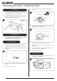
Remote Control
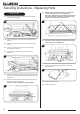
6.9 To remove the gas valve first remove the thermocouple,
see Diagram 27, Arrow A.
A
B
C
D
27
Screw
Screw
6.10 Undo the pilot pipe from the gas valve, see Diagram 27,
Arrow B.
6.11 Undo the inlet pipe from the gas valve, see Diagram 27,
Arrow C.
6.12 Undo the main injector feed pipe from the gas valve,
see Diagram 27, Arrow D.
6.13 Disconnect the ignition lead from the pilot unit.
6.14 Undo 2 screws securing the gas valve to the bracket, see
Diagram 27.
6.15 The gas valve can now be removed from the burner unit.
6.16 To replace the gas valve reverse the above procedure.
6.17 Check for gas leaks.