
Unmanaged Ethernet Switch User's Guide


7
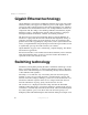
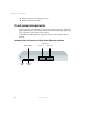
Switch descriptions
www.gateway.com
Gateway 7201-16, 7201-24 (shown), 7201-24.2, and 7401-24 switches
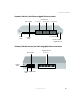
Rear panel description
The rear panels of the switches consists of the power connector only, and are
not shown. The AC power connector (Gateway 7201-16, 7201-24, 7201-24.2,
and 7401-24) is a standard three-pronged connector that supports the power
cord. Plug one end of the power cord into the socket and the other end into
the power outlet. The switch automatically adjusts its power setting to any
supply voltage in the range from 100 ~ 240 VAC at 50 ~ 60 Hz.
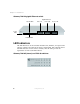
The rear panel of the Gateway 7401-05 and 7401-08 switches consists of the
DC power jack (AC power adapter supplied). The AC power adapter
automatically adjusts its power setting to any supply voltage in the range from
100 ~ 240 VAC at 50 ~ 60 Hz.
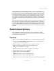
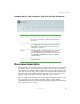
LED Indicates
Power This indicator will light steady green immediately after
the switch is powered on to indicate the ready state of
the device.
Link/Act This indicator lights green when the port is connected
to a Gigabit Ethernet, Fast Ethernet, or Ethernet station.
If the indicator is blinking green, data is either being
transmitted or received.
Speed This LED indicator is dark when the port is connected
to a 10 Mbps Ethernet or 100 Mbps Fast Ethernet
station, and it lights green when the port is connected
to a 1000 Mbps Gigabit Ethernet station (on gigabit
capable models).
Duplex This LED indicator lights green when the port active in
full duplex mode.