Gateway E-842R SAS RAID USERGUIDE ®
Contents Chapter 1: Introduction . . . . . . . . . . . . . . . . . . . . . . . . . . . . . . . . . . . . . . . . . . . 1 Overview . . . . . . . . . . . . . . . . . . . . . . . . . . . . . . . . . . . . . . . . . . . . . . . . . . . . . . . . . . . . . . . . . 2 Expansion enclosure . . . . . . . . . . . . . . . . . . . . . . . . . . . . . . . . . . . . . . . . . . . . . . . . . 2 The enclosure . . . . . . . . . . . . . . . . . . . . . . . . . . . . . . . . . . . . . . . . . . . . . . . . . . . . . . . . . .
Contents Disk I/O module LEDs . . . . . . . . . . . . . . . . . . . . . . . . . . . . . . . . . . . . . . . . . . . . . . .37 Starting the drives . . . . . . . . . . . . . . . . . . . . . . . . . . . . . . . . . . . . . . . . . . . . . . . . . . . . . . . .37 Disk drive LEDs . . . . . . . . . . . . . . . . . . . . . . . . . . . . . . . . . . . . . . . . . . . . . . . . . . . . .37 Starting StorView . . . . . . . . . . . . . . . . . . . . . . . . . . . . . . . . . . . . . . . . . . . . . . . . . . . . . . .
www.gateway.com AC power (350 W power supply module) . . . . . . . . . . . . . . . . . . . . . . . . . . . . . . . . . . . . 58 Power consumption . . . . . . . . . . . . . . . . . . . . . . . . . . . . . . . . . . . . . . . . . . . . . . . . . . . . . . . 59 Power supply module safety and EMC compliance . . . . . . . . . . . . . . . . . . . . . . . . . . . 59 Environment . . . . . . . . . . . . . . . . . . . . . . . . . . . . . . . . . . . . . . . . . . . . . . . . . . . . . . . . . . . . . 59 Interfaces .
Contents vi
CHAPTER1 Introduction • Overview • The enclosure • The plug-in modules 1
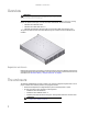
CHAPTER 1: Introduction Overview Important Mixing of SAS and SATA drives in the same enclosure is only supported in columns, for example, column 1 is all SAS and column 2 is all SATA. Also, mixing of drives of different capacities in the same column is not supported. The Gateway E-842R SAS Enclosure Platform is a 2U (rack space) disk drive enclosure, housing twelve low profile (1-inch high), 3.
www.gateway.com • Two plug-in power supply modules, 100-240 V AC, 350 W. • One plug-in cooling fan module. • Two plug-in controller modules, each incorporating a RAID controller and a StorView Management Module. Important If only one controller module is installed, a blank module must be installed in the unused slot. Enclosure chassis The chassis consists of a sheet metal enclosure assembly containing a backplane printed circuit board (PCB) and module runner system.
CHAPTER 1: Introduction Operator’s panel The enclosure’s front panel has an integrated operator’s (Ops) panel with four LEDs. The Ops panel provides you with a high level indication of the operation of the enclosure. See “Ops panel LEDs” on page 8 for details of the LED status conditions. Caution The Ops panel is an integral part of the enclosure assembly and cannot be replaced separately. To replace the Ops panel, you must replace the entire enclosure.
www.gateway.com Audible alarms The Gateway E-842R enclosure includes an audible alarm which indicates when a fault state is present. The following conditions activate the audible alarm: • Fan fault • Voltage out of range • Over temperature • Thermal overrun • System fault • Logical Fault • Power supply module fault When the audible alarm sounds, you can mute it by pressing the Alarm Mute button on the front panel. For more information, see “Audible alarm mute” on page 16.
CHAPTER 1: Introduction Two LEDs mounted on the rear panel of the power supply module indicate the status of the module: Power On & OK (Green) Module Fault (Orange) Status Off Off No AC power (either power supply module) Off On No AC power (this power supply module only) Power supply module fault (over temperature, over voltage, over current, or power supply module fan fail) On Off AC present, power supply module on and OK On On Power supply module fan fault Multiple power supply modules In
www.gateway.com The module has an orange Cooling Module Fault LED.
CHAPTER 1: Introduction Controller module Caution Operation of the enclosure with any modules missing disrupts the airflow and the drives do not receive sufficient cooling. All openings must be filled before operating the enclosure. When only one controller module is installed, a blank module must be installed in the vacant controller module slot at the rear of the enclosure to maintain airflow and ensure correct operation.
www.gateway.com • An RJ45 10/100BaseT Ethernet port lets you connect the controller to a network to enable out-of-band management and monitoring using the embedded StorView GUI software. Important Only shielded, Cat 5 (or better) cables should be used for connection to the Ehternet port for EMC performance. • There is also an RS232 socket which provides an alternative user interface to the RJ45 connector.
CHAPTER 1: Introduction Controller OK Green When lit, this LED indicates that RAID controller activity is normal. Controller fault Orange When lit, this LED indicates that a RAID controller fault has occurred. Ethernet status Green When lit, this LED indicates that the Ethernet port has a valid connection. Orange When lit, this LED indicates that the Ethernet port has activity. Green When lit, these LEDs show I/O activity on the specific port lane indicated.
www.gateway.com Disk I/O module The expansion enclosure houses one or two Disk I/O modules. They provide the drive expansion for the RAID enclosure. When expanding the system, you may add up to four expansion enclosures. This will give you a total of five enclosures including the RAID enclosure. A fully loaded system will provide a total of 60 disk drives. Important Do not mix Disk I/O modules and RAID Controller modules in the same enclosure.
CHAPTER 1: Introduction Drive carrier module The drive carrier module comprises a hard disk mounted in a carrier. Each drive bay houses a single, low profile, 1.0-inch high, 3.5-inch form-factor disk drive in its carrier. The carrier has mounting locations for SAS or SATA drives.
www.gateway.com Dummy carrier modules Dummy carrier modules are provided for fitting in all unused drive bays. They are designed as integral drive module front caps and must be installed in all unused drive bays to maintain a balanced airflow. Blank modules Caution Operation of the enclosure with any modules missing disrupts the airflow and the drives do not receive sufficient cooling. All openings must be filled before operating the enclosure.
CHAPTER 1: Introduction 14
CHAPTER2 Getting Started • • • • • • • • • • • • Introduction Planning your installation Enclosure installation procedures Module installation Enclosure configuration Enclosure cabling - single enclosure Ethernet connection Enclosure cabling - multiple enclosures Drive slot arrangement Power cord connection Grounding checks Management interfaces 15
CHAPTER 2: Getting Started Introduction Caution When connecting the enclosure, use only the power cords supplied or cords which match the specification quoted in “Specifications” on page 29. This chapter explains how to install your enclosure into an industry-standard, 19-inch rack cabinet and configure the enclosure sub-system. Planning your installation Caution Blank modules or dummy carrier modules MUST be installed in ALL unused bays or the enclosure may overheat.
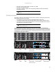
www.gateway.com FACTORY USE ONLY FACTORY USE ONLY PSU 1 PSU 2 Cooling Module Disk I/O Module 0 Disk I/O Module 1 Disk I/O module Enclosure drive bay numbering convention Important Drive carrier modules must always be installed in drive locations 1 and 12. This is the minimum configuration required for the system to operate and provide SES Management Services. The enclosure drive bay numbering convention is shown in the illustration on page 16.
CHAPTER 2: Getting Started Preparing the site and host server Important The E-842R system supports most of the widely used operating systems. However deployment on Microsoft Windows requires the .inf driver file which is found on the Gateway External Storage CD (ESCD). (For Windows Servers, insert the ESCD and install the .inf file.
www.gateway.com Rack installation prerequisites The enclosure is designed for installation into an industry standard, 19-inch cabinet, capable of holding the unit. • A minimum depth of 28 inches (700 mm) from the front flange to the back metalwork (excludes back cabling). • Up to 70.5 lbs (32 kg) per enclosure, depending on configuration.
CHAPTER 2: Getting Started 2 Assemble the left and right chassis latches using the special chassis latch screws. Make sure that the latch is orientated as shown in the following illustration, with the spring arm located against its stop (on the right side at the top, on the left side at the bottom). 3 Assemble the rack brackets to the rack posts as follows: a Fit the location pin at the back of the rail into the rear rail post. b Extend the rail to fit between the front and rear rack posts.
www.gateway.com 4 Mount the enclosure in the rack as follows: a b c d Lift the enclosure and align it with the rack rails. Carefully insert the chassis slides into the rack rails and push it fully into the cabinet. Tighten the rear screws. Withdraw the enclosure until it reaches the hard stops (approximately 15.75 inches (400 mm)). e Return the enclosure to the fully installed position and attach to the rack using the captive thumbscrews on the front flanges.
CHAPTER 2: Getting Started Each E-842R RAID controller module can be connected to up to two independent Host Bus Adaptors. Some typical configurations utilizing one or two RAID controller modules and either one or two HBAs are shown in the following.
www.gateway.com Dual hosts, dual HBAs, and dual controller connections Dual host, single HBA, and dual controller connections Ethernet connection Important Only shielded Cat 5 (or better) cables should be used for connection to the Ethernet port for EMC conformance. An RJ-45 10/100BaseT Ethernet port lets you connect the controller to a network to enable out-of -band management and monitoring using the Embedded StorView GUI software.
CHAPTER 2: Getting Started Enclosure cabling - multiple enclosures You can connect additional expansion enclosures to an E-842R RAID enclosure. Multiple enclosures are connected together using SAS patch cables, up to a maximum of five enclosures, including the RAID enclosure. A typical two-expansion enclosure configuration is shown below.
www.gateway.com Drive location rules The E-842R storage enclosure supports two different types of disk drives, SAS and SATA. In order to allow optimal configurations to be built, the following rules should be observed: Different drive types cannot be mixed in the same column.
CHAPTER 2: Getting Started If you need to change drive technology, a new column of drives should be populated. Column/row 1/# 2/# 3/# 4/# #/1 - SAS 2 SATA 3 - #/2 - SAS 6 SATA 7 - #/3 - - SATA 11 - All members of the column should have the same drive type. Drive start With two active power supply modules installed (required), all drives start immediately.
www.gateway.com Power cord connection Caution Before turning on the enclosure, carry out the grounding checks detailed in “Grounding checks” on page 28. To attach the power cord: 1 Attach the power cords to the power supply modules. The cable strain relief bale fits over and onto the power cord. Lift the bale up first, insert the cable, and secure the bale onto the power cord. Caution The power connections must always be disconnected prior to removal of the power supply module from the enclosure.
CHAPTER 2: Getting Started Management interfaces The following management interfaces are used to configure, manage, and monitor the controller module storage solution. StorView Storage Management software StorView Storage Management software is a full-featured, graphical, HTML-based, software suite designed to configure, manage, and monitor the controller module storage solution.
www.gateway.com Installation If the VDS service is running, it is stopped automatically while the provider is installed. Important The Gateway Hardware Provider for VDS can be installed on a system that already has VDS providers from other vendors. Likewise, other VDS providers can be installed after Gateway’s without any conflict. To install the hardware provider for VDS: Double-click the installer executable. 1 2 3 4 Read the license agreement, then click I Agree to accept to the terms and conditions.
CHAPTER 2: Getting Started 30 Object Method name IVdsAsync QueryStatus Wait IVdsController GetPortProperties GetProperties GetSubSystem Reset SetStatus QueryAssociatedLuns Initialize (internal) IVdsControllerControllerPort QueryControllerPorts IVdsControllerPort Initialize (internal) GetController GetProperties IVdsDrive GetProperties GetSubsystem ClearFlags SetFlags SetStatus Initialize (internal) IVdsHwProvider QuerySubSystems Reenumerate Refresh IVdsHwProviderPrivate QueryIfCreatedLun I
www.gateway.
CHAPTER 2: Getting Started • There are minimum allowable chunk sizes for RAID 0 and RAID 1 arrays (RAID 5 arrays have no restrictions): RAID 0: Number of Drives 1 or 2 3 4 or more Minimum Chunk Size 256K 128K 64K Number of Drives 2 or 4 6 8 or more Minimum Chunk Size 256K 128K 64K RAID 1: Stripe size = (chunk size) x (number of non-parity drives in the array).
www.gateway.
CHAPTER3 Operation • • • • • Before you begin Power on Starting the drives Starting StorView Power down 7
CHAPTER 3: Operation Before you begin Before turning on the enclosure, make sure that all the modules are firmly seated in their correct bays. Power on Caution Do not operate this equipment until the ambient temperature is within the specified operating range. If the drives have been recently installed, make sure that they have time to acclimatize before operating them. Important See “Ops panel LEDs” on page 8 for details of the Ops panel LEDs and related fault conditions.
www.gateway.com Disk I/O module LEDs The disk I/O module LEDs status conditions are defined in “Disk I/O module LEDs” on page 15. Starting the drives Unless otherwise selected during installation, all drives in the enclosure should start automatically. If they do not start, there may be a power problem (an alarm and power fault indication would normally be active). Disk drive LEDs Each drive carrier incorporates two indicators, an upper (green) and lower (orange).
CHAPTER 3: Operation 10
CHAPTER4 Troubleshooting • • • • • • • • • • • Overview Status indicator LEDs Audible alarm Drive carrier module faults Troubleshooting Hardware faults Continuous operation during replacement Replacing a module Power supply modules Drive carrier module Telephone support 11
CHAPTER 4: Troubleshooting Overview The Gateway E-842R enclosure includes a processor and associated monitoring and control logic to enable it to diagnose problems within the enclosure’s power, cooling, and drive systems. The sensors for power and cooling conditions are housed within the power supply modules. There is independent monitoring for each unit. If a fault is indicated on the Ops panel, see the table in “Ops panel LEDs” on page 14.
www.gateway.com • Check the controller module setup as follows: Important For details on how to remove and replace a plug-in module, see “Replacing a module” on page 19. • Make sure that the controller module has been correctly installed and all external links and cables are connected securely. • Make sure that the maximum cable length has not been exceeded. • Make sure that the RAID controller module is correctly set up at the Management Interface.
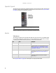
CHAPTER 4: Troubleshooting Ops panel LEDs Important The Ops panel is supplied as an integral part of the enclosure core product and is not user replaceable. The Ops panel displays the overall status of all the modules. The Ops panel LEDs are described in the following table.
www.gateway.com Controller module LEDs For details on how to remove and replace a controller module see “Controller module” on page 22. The controller module incorporates the following LED indicators: LED functions LED state Definition Battery fault Orange When lit, this LED indicates that the backup battery unit is missing, has low voltage, has experienced a time-out on charge, indicated a faulty battery, or has experienced a fault in the charging circuitry.
CHAPTER 4: Troubleshooting Audible alarm mute When the audible alarm sounds, you can mute it by pressing the alarm mute button, located on the enclosure’s front panel. Automatic muting takes place after two minutes if you do not press the alarm mute button. When the alarm is muted, it continues to sound with short intermittent beeps to indicate that a problem still exists. The alarm turns off when all problems are cleared. (See “Thermal warnings” on page 18).
www.gateway.com Troubleshooting The following sections describe problems, with possible solutions, which can occur with your Gateway E-842R Storage Area Network. System faults Symptom Cause Action 1. The CONTROLLER FAULT LED lights orange on the module. 2. The audible alarm sounds. The ESI processor has detected an internal fault on one of the following modules: ■ Power supply ■ Cooling ■ RAID Replace the faulty module as appropriate. Also see “Thermal warnings” on page 18.
CHAPTER 4: Troubleshooting Thermal alarm Symptom ■ ■ ■ ■ Cause Ops panel SYSTEM FAULT LED is orange. An orange LED on one or more power supply module. An audible alarm is sounding. Air temperature in the exiting power supply module is above 131°F (55°C). If the internal temperature measured in the airflow through the enclosure exceeds a pre-set threshold, a thermal alarm sounds. Cooling module failure.
www.gateway.com Continuous operation during replacement Important The power supply module replacement time must be as short as possible because the Gateway E-842R enclosure is designed to operate with two power supply modules installed. Important The fans within the cooling module are not user replaceable. In the event of a cooling fan failure, the complete cooling module must be replaced.
CHAPTER 4: Troubleshooting Warning Do not remove covers from the power supply modules. There is a danger of electric shock inside. To remove a power supply module: 1 Make sure that you identify the faulty power supply module correctly. The Module Fault LED on the faulty power supply module lights orange. 2 Disconnect the power supply cord. 3 Push the latch on the power supply module handle to the right, then grip the handle and pull the power supply module out of the enclosure.
www.gateway.com 4 Connect the power supply cord to the power source. Important The alarm sounds until the new power supply module is operating correctly. Cooling module Removing the cooling module To remove the cooling module: 1 Grasp the latch between your thumb and forefinger. Squeeze your thumb and forefinger together to release the latch. 2 Pull the latch outward to pull the module out of the enclosure. 3 Remove the module.
CHAPTER 4: Troubleshooting Installing the cooling module Caution Handle the module carefully and avoid damaging the connector pins. Do not install the module if any pins appear to be bent. To install the cooling module: 1 Check for damage, especially to the rear connector on the supply. 2 With the latch in the open position, slide the module into the enclosure until the latch engages automatically. 3 Secure the module by manually closing the latch. You should hear a click when the module latch engages.
www.gateway.com 3 Grip the latch handles and remove the module. Installing a RAID controller module To install a RAID controller module: 1 Check for damage, especially to the interface connector. Do not install if the pins are bent. 2 With the latches in the open position, slide the RAID controller module into the enclosure until the latches engage automatically.
CHAPTER 4: Troubleshooting 3 Secure the module by manually closing the latches. You should hear a click when the latches engage. The controller module takes up to one minute to re-initialize onto the loop after re-cabling. Battery module Warning There is a danger of explosion if the battery is incorrectly replaced. Dispose of used batteries in accordance with the manufacturer’s instructions and national regulations.
www.gateway.com Removing a battery module To remove a battery module: • Operate the release latch and slide the battery module out of the controller module. Installing a battery module To install a battery module: 1 Check for damage. Do not install if there are any outer signs of damage. 2 Slide the battery module into the vacant slot on the right side of the controller module until it clicks into place.
CHAPTER 4: Troubleshooting Drive carrier module Caution Observe all conventional ESD precautions when handling modules and components. Avoid contact with such things as backplane components and module connectors. Removing a drive carrier module To remove a drive carrier module: 1 Release the carrier handle by pressing the latch in the handle towards the right. The anti-tamper lock must be off. Caution Damage can occur to a drive if it is removed while still spinning.
www.gateway.com Installing a drive carrier module Caution All drive bays must have drive carrier modules or dummy carrier modules installed to maintain a balanced airflow. Dummy carrier modules are provided for fitting in all unused drive bays. They are designed as integral drive module front caps and must be installed in all unused drive bays to maintain a balanced airflow.
CHAPTER 4: Troubleshooting 3 Secure the carrier into the slot (the latch on the base of the carrier engages a slot in the enclosure). Continue to push firmly until the handle fully engages. You should hear a click when the latch engages and holds the handle closed. Dummy drive carrier module removal and replacement Dummy drive carrier modules are removed and replaced in the enclosure by pulling the dummy module out of the enclosure or pushing it into place.
APPENDIXA Specifications • • • • • • • • • Dimensions Weight AC power (350 W power supply module) Power supply module safety and EMC compliance Environment Interfaces Controller module specification Disk I/O module specification Drive carrier module specification 29
APPENDIX A: Specifications Dimensions Enclosure inches mm Height 3.46 87.9 Width across the mounting flange 19 483 Width across the body of the enclosure 17.6 447 Depth from the flange to the rear of the enclosure body 21.65 550 Depth from the flange to the maximum extremity of enclosure (rear hold down) 22.72 577 Depth from the flange to the furthest extremity at the front of the enclosure 1.44 36.5 We recommend that a rack with a depth of no less than 27.
www.gateway.com Power consumption Power consumption of enclosure with 12x SAS drives running I/O, powered by a single power supply module (Power One power supply module) with extended power lead between the power supply module and the I/O backplane and with two controllers installed at IDLE and ACTIVE operation. Caution The enclosure must be operated with two power supplies in place. Voltage Rail IDLE ACTIVE Average Peak Average Peak 5V 11.51A 13.2A 13.53A 15.7A 12V 12.29A 15.1A 13.17A 20.
APPENDIX A: Specifications Shock, Operational Vertical axis 5 g peak 1/2 sine, 10 ms Shock, Non-Operational 30 g 10 ms 1/2 sine Vibration, Operational 0.21 grms 5-500 Hz Random Vibration, Non-Operational 1.04 grms 2-200 Hz Random Vibration, Relocation 0.3 g 2-200 Hz sine Acoustics Sound Power Operating: Less than 58 dB LwA measured at 73.4°F (23°C). Sound Pressure Operating: Less than 6.8 Bels LwA measured at 73.4°F (23°C).
www.gateway.com LED functions LED functions LED state Definition Battery fault Orange When lit, this LED indicates that the backup battery unit is missing, has low voltage, has experienced a time-out on charge, indicated a faulty battery, or has experienced a fault in the charging circuitry. Cache active Orange When lit, this LED indicates that the RAID controller cache has data saved in memory but not written to the disk array.
APPENDIX A: Specifications Drive carrier module specification Important Operating E-842R enclosures with non-approved drives may invalidate the warranty. Contact Gateway Customer Care for details of approved drives. The drive carrier module is not available separately. 34 Module dimensions Height 1.06” (27.05 mm( Width 4.19” (106.55 mm) Depth 8.25” (209.55 mm) Weight 1.91 lbs (0.86 kg) (with 1.
APPENDIXB Legal Information 35
APPENDIX B: Legal Information Regulatory compliance statements United States of America Federal Communications Commission (FCC) Unintentional emitter per FCC Part 15 FCC Part 15 Class A Statement The server is designated as complying with Class A requirements if it bares the following text on the rating label: This device complies with Part 15 of the FCC Rules. Operation is subject to the following two conditions: (1) This device may not cause harmful interference.
www.gateway.com For unique identification of the product configuration, please submit the 10-digit serial number found on the product to the responsible party. Caution Changes or modifications not expressly approved by Gateway could void the FCC compliance and negate your authority to operate the product. This device complies with Part 15 of the FCC Rules.
APPENDIX B: Legal Information Environmental information The product you have purchased contains extracted natural resources that have been used in the manufacturing process. This product may contain substances known to be hazardous to the environment or to human health.
APPENDIXC Safety Information 39
APPENDIX C: Safety Information Important safety information Warning Always follow these instructions to help guard against personal injury and damage to your Gateway system. Your Gateway system is designed and tested to meet the latest standards for safety of information technology equipment. However, to ensure safe use of this product, it is important that the safety instructions marked on the product and in the documentation are followed.
Index A H T accessories HBA 18 safety precautions 68 help alarm mute button 44 telephone support 56 anti-static wrist or ankle strap 18 Host Bus Adaptors (HBAs) 23 anti-tamper lock 12, 27, 54 I Audible Alarm 43, 44, 45, 46 IEC 320 connector 28 audible alarm 5, 43, 45, 46 auto start failure 44 telephone support 56 troubleshooting telephone support 56 U Unpacking the Enclosure System 18 UPS 18 L B backplane 2, 3, 18, 47, 54 bay 16 C CD External Storage 18, 19 chassis 3 controller module 52 D disc 3
Index 70
A MAN E-842R SAS USR GDE R0 05/07