Service Guide Gateway M350 Notebook
Thank you for purchasing this Factory Service Manual CD/DVD from servicemanuals4u.com.
Contents Replacing Gateway M350 Components. . . . . . . . . . . . . . . . . . . . . . . . . . . . . . 1 Identifying the notebook model . . . . . . . . . . . . . . . . . . . . . . . . . . . . . . . . . . . . . . . . . 2 Identifying components . . . . . . . . . . . . . . . . . . . . . . . . . . . . . . . . . . . . . . . . . . . . . . . 3 Preparing your work space . . . . . . . . . . . . . . . . . . . . . . . . . . . . . . . . . . . . . . . . . . . . 4 Preventing static electricity discharge . . . . . . . . .
ii
Replacing Gateway M350 Components Important This service guide is not intended to be provided to individual users or consumers. It cannot be provided to anyone other than an authorized service provider. Use this service guide to help plan your maintenance tasks for the Gateway M350 notebook. All tasks covered in this guide can be performed by an authorized field technician without jeopardizing the notebook’s warranty.
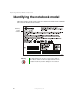
Replacing Gateway M350 Components Identifying the notebook model The label on the bottom of the notebook contains information that identifies the notebook model and its features. Gateway model number Warning 2 It is important that you use the correct service guide for the notebook. Failure to follow the approved tasks for the notebook model may result in damage to the notebook. www.gateway.
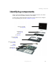
Identifying components Identifying components Where screw measurements are shown, the first number indicates screw head width, and the second number indicates screw length. Use this chart to identify the main components of the notebook. For a complete list of replaceable parts, see the “Contents” on page i.
Replacing Gateway M350 Components Preparing your work space Before performing maintenance on the notebook, make sure that your work space and the notebook are correctly prepared. 4 ■ Wear a grounding (ESD) wrist strap, and use a grounded or dissipative work mat. ■ Use a stable and strong table, and make sure that the table top is large enough to hold each component as you remove it. ■ Use bright lighting to make part identification easier.
Preventing static electricity discharge Preventing static electricity discharge The components inside the notebook are extremely sensitive to static electricity, also known as electrostatic discharge (ESD). Warning ESD can permanently damage electrostatic discharge-sensitive components in the notebook. Prevent ESD damage by following ESD guidelines every time you open the notebook case.
Replacing Gateway M350 Components Before working with notebook components, follow these guidelines: ■ Avoid static-causing surfaces such as carpeted floors, plastic, and packing foam. ■ Remove components from their antistatic bags only when you are ready to use them. Do not lay components on the outside of antistatic bags because only the inside of the bags provide electrostatic protection. ■ Always hold components by their edges. Avoid touching the edge connectors.
Removing the battery Removing the battery To remove the battery: 1 Disconnect the AC adapter and modem and network cables and prepare the notebook by following the instructions in “Preparing the notebook” on page 6. 2 3 Turn the notebook over so the bottom is facing up. Slide the battery release latch. www.gateway.
Replacing Gateway M350 Components 4 8 Lift the battery out of the bay. www.gateway.
Replacing the hard drive kit Replacing the hard drive kit Tools you need to complete this task: Phillips #0 screwdriver Screws removed during this task: 2 chrome 2.5 × 6 mm (hard drive kit) Hard drive www.gateway.
Replacing Gateway M350 Components To replace the hard drive kit: 1 Disconnect the AC adapter and modem and network cables and prepare the notebook by following the instructions in “Preparing the notebook” on page 6. 2 3 Turn the notebook over so the bottom is facing up. 4 Remove the two hard drive kit screws. Remove the battery by following the instructions in “Removing the battery” on page 7. Screws Tips & Tricks 10 Use a magnetic screwdriver or turn the notebook over to remove the screws.
Replacing the hard drive kit 5 Slide the old hard drive kit away from the connector. 6 Lift the end of the hard drive kit furthest from the connector, then remove the kit from the bay. www.gateway.
Replacing Gateway M350 Components 7 8 12 Place the new hard drive kit into the bay and slide it into the connector. Replace the screws that secure the hard drive kit to the notebook. www.gateway.
Replacing the hard drive in the hard drive kit Replacing the hard drive in the hard drive kit Tools you need to complete this task: Phillips #0 screwdriver Screws removed during this task: 2 chrome 2.5 × 6 mm (hard drive kit) 4 chrome 3 × 3.5 mm (hard drive) To replace the hard drive in the hard drive kit: 1 Disconnect the AC adapter and modem and network cables and prepare the notebook by following the instructions in “Preparing the notebook” on page 6.
Replacing Gateway M350 Components 5 Remove the four screws that secure the hard drive to the hard drive kit bracket. Screw Screw 14 6 Remove the bracket from the old drive. 7 8 Insert the new drive into the bracket so the screw holes line up. Replace the four screws that secure the bracket to the drive. www.gateway.
Replacing the hard drive in the hard drive kit 9 10 Slide the new hard drive kit into the notebook. Replace the screws that secure the hard drive kit to the notebook. www.gateway.
Replacing Gateway M350 Components Replacing the optical drive Tools you need to complete this task: Phillips #0 screwdriver Screws removed during this task: 2 chrome 2.5 × 6 mm (Optical drive) To replace the hard drive in the hard drive kit: 16 1 Disconnect the AC adapter and modem and network cables and prepare the notebook by following the instructions in “Preparing the notebook” on page 6. 2 3 Turn the notebook over so the bottom is facing up.
Replacing the optical drive 4 Remove the two optical drive screws. Screws 5 Slide the old drive out of your notebook. Tips & Tricks To make removing the optical drive easier, insert a straightened paperclip into the manual eject hole on the optical drive. Grab the open optical drive tray and pull the drive straight out. www.gateway.
Replacing Gateway M350 Components 18 6 Slide the new drive into your notebook. 7 Replace the two optical drive screws. www.gateway.
Replacing the keyboard cover Replacing the keyboard cover Tools you need to complete this task: Flat-blade driver - OR - Scribe or non-marring tool To replace the keyboard cover: 1 Disconnect the AC adapter and modem and network cables and prepare the notebook by following the instructions in “Preparing the notebook” on page 6. 2 3 Turn the notebook over so the bottom is facing up. 4 5 Turn the notebook over so the top is facing up.
Replacing Gateway M350 Components 6 Insert the small flat-blade screwdriver or non-marring tool under the bottom right corner of the keyboard cover and gently pry it up. Important 20 Inserting a piece of cloth between the screwdriver and keyboard and notebook case will help prevent damage to the notebook. www.gateway.
Replacing the keyboard cover 7 Pull the cover off the notebook. You will hear small snapping sounds as the cover comes away from the notebook. Be careful not to break off the tabs found on the left end of the cover. 8 Slide the two tabs on the left end of the new cover under the notebook frame. www.gateway.
Replacing Gateway M350 Components 9 Press down on the cover in several places until it clicks in place. The cover is correctly mounted when you can run you finger along the cover and find no loose spots. The cover should be flat all the way across. Warning 22 If the cover is not correctly replaced, the notebook could be damaged when you try to close the LCD panel. www.gateway.
Replacing the keyboard Replacing the keyboard Tools you need to complete this task: Flat-blade driver - OR - Scribe or non-marring tool Phillips #0 screwdriver Screws removed during this task: 4 chrome 2.5 × 2.5 mm (keyboard) To replace the keyboard: 1 Disconnect the AC adapter and modem and network cables and prepare the notebook by following the instructions in “Preparing the notebook” on page 6. 2 3 Turn the notebook over so the bottom is facing up.
Replacing Gateway M350 Components 6 Remove the four keyboard screws that secure the keyboard to the notebook. Screws 7 24 Lift the back edge of the keyboard slightly, then carefully slide the keyboard back until the four tabs on the front edge of the keyboard are free from their slots. Be careful not to damage the LCD panel. www.gateway.
Replacing the keyboard 8 Slowly rotate the keyboard toward you so it lies keys-down on top of the notebook. Be careful not to damage the LCD panel. 9 Carefully insert the small flat-blade screwdriver between the keyboard cable and the black plastic hinge where the cable connects to the system board. Gently lift the hinge off the cable. The cable is now free and you can remove the keyboard. 10 Place the new keyboard keys-down on the notebook with the space bar away from you. www.gateway.
Replacing Gateway M350 Components 11 Verify the black plastic hinge on the system board keyboard connector is in the raised position. 12 Insert the end of the keyboard cable between the black plastic hinge and the white connector. Important The cable is correctly oriented if it is not twisted. 13 14 Press the black plastic hinge onto the keyboard cable. 15 Insert the four tabs located on the front edge of the keyboard into the corresponding slots under the palm rest.
Replacing the keyboard 17 Replace the four keyboard screws. Screws 18 Reassemble the notebook. www.gateway.
Replacing Gateway M350 Components Adding or replacing memory modules Adding or replacing memory in the memory bay Tools you need to complete this task: Phillips #0 screwdriver Important Use only memory modules designed for the Gateway M350. Memory bay 28 www.gateway.
Adding or replacing memory modules To add or replace memory modules: 1 Disconnect the AC adapter and modem and network cables and prepare the notebook by following the instructions in “Preparing the notebook” on page 6. 2 3 Turn the notebook over so the bottom is facing up. 4 Loosen the five captive memory bay cover screws, then remove the memory bay cover. These screws cannot be removed. Remove the battery by following the instructions in “Removing the battery” on page 7. Screws Screws www.
Replacing Gateway M350 Components 30 5 If you are removing a module, gently press outward on the clip at each end of the memory module until the module tilts upward. 6 Pull the memory module out of the slot. 7 Hold the new or replacement module at a 30-degree angle and press it into the empty memory slot. This module is keyed so it can only be inserted in one direction. If the module does not fit, make sure that the notch in the module lines up with the tab in the memory bay.
Adding or replacing memory modules Replacing memory under the keyboard Tools you need to complete this task: Flat-blade driver - OR - Scribe or non-marring tool Phillips #0 screwdriver Screws removed during this task: 4 chrome 2.5 × 2.5 mm (keyboard) Important Use only memory modules designed for the Gateway M350 for upgrading your memory.
Replacing Gateway M350 Components 6 Remove the keyboard cover by following the instructions in “Replacing the keyboard cover” on page 19. 7 Open the keyboard compartment by following the instructions in “Replacing the keyboard” on page 23. Important 8 Gently press outward on the clip at each end of the memory module until the module tilts upward. 9 Pull the memory module out of the slot. 10 32 You do not need to disconnect the keyboard from the system board.
Adding or replacing memory modules 11 12 Gently push the module down until it clicks in place. Reassemble the notebook. www.gateway.
Replacing Gateway M350 Components Replacing the IEEE 802.11 Mini PCI card Caution By law, only approved wireless modules provided by Gateway, or a Gateway authorized representative, explicitly for the Gateway M350 may be installed in this notebook. Tools you need to complete this task: Flat-blade driver - OR - Scribe or non-marring tool Phillips #0 screwdriver Screws removed during this task: 4 chrome 2.5 × 2.5 mm (keyboard) To replace the IEEE 802.
Replacing the IEEE 802.11 Mini PCI card 6 Remove the keyboard cover by following the instructions in “Replacing the keyboard cover” on page 19. 7 Open the keyboard compartment by following the instructions in “Replacing the keyboard” on page 23. Important 8 You do not need to disconnect the keyboard from the system board. Unplug the two antenna cables. www.gateway.
Replacing Gateway M350 Components 9 10 36 Move the antenna wires out of the way, then press outward on the clip at each side of the module until the module tilts upward. Pull the module out of the slot. www.gateway.
Replacing the IEEE 802.11 Mini PCI card 11 Hold the new module at a 30-degree angle and press it into the empty slot. This module is keyed so it can only be inserted in one direction. If the module does not fit, make sure that the notch in the module lines up with the tab in the module slot. 12 Move the antenna wires out of the way, then press the module down until it clicks into place.
Replacing Gateway M350 Components Replacing the cooling assembly Tools you need to complete this task: Phillips #0 screwdriver To replace the cooling assembly: 38 1 Disconnect the AC adapter and modem and network cables and prepare the notebook by following the instructions in “Preparing the notebook” on page 6. 2 3 Turn the notebook over so the bottom is facing up. 4 Loosen the five captive memory bay cover screws, then remove the memory bay cover. These screws cannot be removed.
Replacing the cooling assembly 6 Loosen the five captive screws that secure the cooling assembly to the notebook. These screws cannot be removed. Screws Screws 7 8 Remove the cooling assembly. If the new cooling assembly came with a blue plastic cover that covers the thermal grease on the bottom side of the new cooling assembly, remove it. Go to Step 10. -ORIf the new cooling assembly did not come with thermal grease already applied, go to Step 9.
Replacing Gateway M350 Components 10 Remove any thermal grease residue that may remain on the processor from the old cooling assembly. The residue can be removed using Isopropyl Alcohol, Acetone, or Toluene and a lint free cloth. 11 12 Insert the new cooling assembly into the notebook. Tighten the five cooling assembly screws in the order. Make sure that you tighten the screws in numerical order. Each screw hole has a numeral next to it.
Replacing the hinge covers Replacing the hinge covers Tools you need to complete this task: Flat-blade driver - OR - Scribe or non-marring tool Phillips #0 screwdriver Screws removed during this task: 4 chrome 2.5 × 2.5 mm (keyboard) 4 black 2.5 × 5 mm (hinge covers) To replace the hinge covers: 1 Disconnect the AC adapter and modem and network cables and prepare the notebook by following the instructions in “Preparing the notebook” on page 6.
Replacing Gateway M350 Components 6 Open the keyboard compartment by following the instructions in “Replacing the keyboard” on page 23. Important 7 8 You do not need to disconnect the keyboard from the system board. Open the LCD panel all the way. Remove the hinge cover screws for the cover you are replacing. Left hinge cover screws 42 Right hinge cover screws www.gateway.
Replacing the hinge covers 9 Insert the small flat-blade screwdriver or non-marring tool under the bottom of the hinge cover, then carefully pry it up. Press down on the two plastic screw tabs while you pry. Warning 10 To avoid breaking the hinge cover or putting stress on the LCD panel, hold down on the two plastic screw tabs while you pry. Snap the new cover into place over the hinge. www.gateway.
Replacing Gateway M350 Components 11 12 44 Replace the hinge cover screws. Reassemble the notebook. www.gateway.
Replacing the LCD panel assembly Replacing the LCD panel assembly Tools you need to complete this task: Flat-blade driver - OR - Scribe or non-marring tool Phillips #0 screwdriver Screws removed during this task: 4 chrome 2.5 × 2.5 mm (keyboard) 4 black 2.5 × 5 mm (hinge covers) 4 chrome 2.
Replacing Gateway M350 Components 6 Open the keyboard compartment by following the instructions in “Replacing the keyboard” on page 23. Important 7 If the notebook has IEEE 802.11 wireless networking built in, detach the two antenna cables. 8 Remove both hinge covers by following the instructions in “Replacing the hinge covers” on page 41. 9 Use the plastic tab to carefully unplug the LCD video cable from the notebook. Make sure you grasp the tab, not the cable.
Replacing the LCD panel assembly 10 Remove the four hinge screws that secure the LCD panel to the notebook. Note the location of the LCD panel grounding wires attached to one of the left and right hinge screws. Screws 11 Screws Lift the LCD panel assembly away from the notebook. The LCD panel assembly is now completely detached from the notebook. Warning The IEEE 802.11 connectors may catch on the EMI shielding. Be careful not to break off the connectors on the antenna cable.
Replacing Gateway M350 Components Replacing the palm rest assembly Tools you need to complete this task: Flat-blade driver - OR - Scribe or non-marring tool Phillips #0 screwdriver Screws removed during this task: 4 chrome 2.5 × 2.5 mm (keyboard) 4 black 2.5 × 5 mm (hinge covers) 10 chrome 2.5 × 6 mm (bottom, palm rest) 3 chrome 2.5 × 3.5 mm (bottom, palm rest) 4 chrome 2.5 × 6 mm (back, palm rest) 48 www.gateway.com 4 chrome 2.5 × 6 mm (LCD panel hinges) 6 black 2.
Replacing the palm rest assembly To replace the palm rest assembly: 1 Disconnect the AC adapter and modem and network cables and prepare the notebook by following the instructions in “Preparing the notebook” on page 6. 2 3 Turn the notebook over so the bottom is facing up. 4 Remove the hard drive kit by following the instructions in “Replacing the hard drive kit” on page 9. 5 6 Turn the notebook over so the top is facing up.
Replacing Gateway M350 Components 10 Turn the notebook over, then remove the thirteen screws on the bottom of the notebook. Screws Screws Screws Screws Important 50 The three shorter screws fit into the battery bay. www.gateway.
Replacing the palm rest assembly 11 Turn the notebook over, then remove the seven screws on the top of the notebook. Screws Important 12 The chrome screw fits in the silver EMI shield. Remove the four screws on the back of the notebook. Screws www.gateway.
Replacing Gateway M350 Components 13 Carefully insert the small flat-blade screwdriver between the touchpad cable and the black plastic hinge where the cable connects to the system board. Gently lift the hinge off the cable. The cable is now free. 14 15 Lift the palm rest assembly completely from the notebook. 16 Replace all of the palm rest screws. Place the new palm rest assembly onto the notebook, then snap the assembly into place.
Replacing the palm rest assembly 18 Insert the end of the touchpad cable between the black plastic hinge and the white connector. Important 19 20 The cable is oriented correctly if it is twisted as shown in the previous picture and the blue side is visible. Press the black plastic hinge onto the touchpad cable. Reassemble the notebook. www.gateway.
Replacing Gateway M350 Components Replacing the diskette drive Tools you need to complete this task: Flat-blade driver - OR - Scribe or non-marring tool Phillips #0 screwdriver Screws removed during this task: 4 chrome 2.5 × 2.5 mm (keyboard) 4 black 2.5 × 5 mm (hinge covers) 10 chrome 2.5 × 6 mm (bottom, palm rest) 3 chrome 2.5 × 3.5 mm (bottom, palm rest) 4 chrome 2.5 × 6 mm (back, palm rest) 54 4 chrome 2.5 × 6 mm (LCD panel hinges) 6 black 2.5 × 5 mm (top, palm rest) 1chrome 2.5 × 2.
Replacing the diskette drive To replace the diskette drive: 1 Disconnect the AC adapter and modem and network cables and prepare the notebook by following the instructions in “Preparing the notebook” on page 6. 2 3 Turn the notebook over so the bottom is facing up. 4 5 Turn the notebook over so the top is facing up. 6 Remove the keyboard by following the instructions in “Replacing the keyboard” on page 23.
Replacing Gateway M350 Components 10 Remove the three screws that secure the diskette drive to the notebook. Screws Screw 56 www.gateway.
Replacing the diskette drive 11 Carefully insert the small flat-blade screwdriver between the diskette drive cable and the black plastic hinge where the cable connects to the system board. Gently lift the hinge off the cable. The cable is now free. 12 Make sure that the black plastic hinge on the system board diskette drive connector is in the raised position. 13 Insert the end of the diskette drive cable between the black plastic hinge and the white connector.
Replacing Gateway M350 Components Replacing the memory card reader Tools you need to complete this task: Flat-blade driver - OR - Scribe or non-marring tool Phillips #0 screwdriver Screws removed during this task: 4 chrome 2.5 × 2.5 mm (keyboard) 4 black 2.5 × 5 mm (hinge covers) 10 chrome 2.5 × 6 mm (bottom, palm rest) 3 chrome 2.5 × 3.5 mm (bottom, palm rest) 4 chrome 2.5 × 6 mm (back, palm rest) 58 4 chrome 2.5 × 6 mm (LCD panel hinges) 6 black 2.5 × 5 mm (top, palm rest) 1chrome 2.5 × 2.
Replacing the memory card reader To replace the memory card reader: 1 Disconnect the AC adapter and modem and network cables and prepare the notebook by following the instructions in “Preparing the notebook” on page 6. 2 3 Turn the notebook over so the bottom is facing up. 4 5 Turn the notebook over so the top is facing up. 6 Remove the keyboard by following the instructions in “Replacing the keyboard” on page 23.
Replacing Gateway M350 Components 10 Remove the three screws that secure the memory card reader to the notebook. Screws Screw 60 www.gateway.
Replacing the memory card reader 11 Unplug the card reader cable from the system board. 12 13 14 Connect the new card reader cable into the system board. Replace the three screws that secure the card reader to the notebook. Reassemble the notebook. www.gateway.
Replacing Gateway M350 Components Replacing the modem Tools you need to complete this task: Flat-blade driver - OR - Scribe or non-marring tool Phillips #0 screwdriver Screws removed during this task: 4 chrome 2.5 × 2.5 mm (keyboard) 4 black 2.5 × 5 mm (hinge covers) 10 chrome 2.5 × 6 mm (bottom, palm rest) 3 chrome 2.5 × 3.5 mm (bottom, palm rest) 4 chrome 2.5 × 6 mm (back, palm rest) 62 4 chrome 2.5 × 6 mm (LCD panel hinges) 6 black 2.5 × 5 mm (top, palm rest) 1chrome 2.5 × 2.
Replacing the modem To replace the modem: 1 Disconnect the AC adapter and modem and network cables and prepare the notebook by following the instructions in “Preparing the notebook” on page 6. 2 3 Turn the notebook over so the bottom is facing up. 4 5 Turn the notebook over so the top is facing up. 6 Remove the keyboard by following the instructions in “Replacing the keyboard” on page 23. 7 Remove both hinge covers by following the instructions in “Replacing the hinge covers” on page 41.
Replacing Gateway M350 Components 64 12 Turn the modem over, then unplug the modem cable from the modem. 13 14 Connect the modem cable into the new modem. 15 16 Replace the two screws that secure the modem to the notebook. Align the modem’s screw holes with the holes on the notebook, then press the modem into place. Reassemble the notebook. www.gateway.
Replacing the CMOS battery Replacing the CMOS battery Tools you need to complete this task: Flat-blade driver - OR - Scribe or non-marring tool Phillips #0 screwdriver Screws removed during this task: 4 chrome 2.5 × 2.5 mm (keyboard) 4 black 2.5 × 5 mm (hinge covers) 10 chrome 2.5 × 6 mm (bottom, palm rest) 3 chrome 2.5 × 3.5 mm (bottom, palm rest) 4 chrome 2.5 × 6 mm (LCD panel hinges) 6 black 2.5 × 5 mm (top, palm rest) 1chrome 2.5 × 2.5 mm (top, palm rest) 4 chrome 2.
Replacing Gateway M350 Components To replace the CMOS battery: 66 1 Disconnect the AC adapter and modem and network cables and prepare the notebook by following the instructions in “Preparing the notebook” on page 6. 2 3 Turn the notebook over so the bottom is facing up. 4 5 Turn the notebook over so the top is facing up. 6 Remove the keyboard by following the instructions in “Replacing the keyboard” on page 23.
Replacing the CMOS battery 10 Locate the old battery on the system board. CMOS battery 11 Insert the small flat-blade screwdriver or non-marring tool under the old battery and gently pry it up until it pops out of the socket. 12 Make sure the positive (+) side of the new battery is facing up, then press the battery into the socket until it snaps into place. 13 Reassemble the notebook. www.gateway.
Replacing Gateway M350 Components Replacing the system board Tools you need to complete this task: Flat-blade driver - OR - Phillips #0 screwdriver 68 www.gateway.com Scribe or non-marring tool 5.
Replacing the system board Screws removed during this task: 2 chrome 2.5 × 6 mm (hard drive kit) 4 black 2.5 × 5 mm (hinge covers) 2 chrome 2.5 × 6 mm (Optical drive) 4 chrome 2.5 × 6 mm (LCD panel hinges) 6 black 2.5 × 5 mm (top, palm rest) 1chrome 2.5 × 2.5 mm (top, palm rest) 10 chrome 2.5 × 6 mm (bottom, palm rest) 3 chrome 2.5 × 3.5 mm (bottom, palm rest) 4 chrome 2.5 × 6 mm (back, palm rest) 4 chrome 2.5 × 2.5 mm (keyboard) 3 black 2.
Replacing Gateway M350 Components To replace the system board: 1 Disconnect the AC adapter and modem and network cables and prepare the notebook by following the instructions in “Preparing the notebook” on page 6. 2 Identify the correct system board installed in the notebook. Warning Two different system boards are used in the Gateway M350 notebook, depending on date of manufacture. When replacing the system board, be sure that the new system board is the same model as the old system board.
Replacing the system board 6 Remove the optical drive by following the instructions in “Replacing the optical drive” on page 16. 7 Remove the bottom memory module by following the instructions in “Adding or replacing memory in the memory bay” on page 28. 8 Remove the cooling assembly by following the instructions in “Replacing the cooling assembly” on page 38. 9 10 Turn the notebook over so the top is facing up.
Replacing Gateway M350 Components 72 19 Unplug the speakers from the system board (one connector). 20 Unplug the audio board from the system board. www.gateway.
Replacing the system board 21 Unplug the front LED panel from the system board. 22 Remove the four hex nuts on the rear I/O panel. Hex nuts www.gateway.
Replacing Gateway M350 Components 23 Remove the seven system board screws and the two system board hex nuts. Hex nuts Screws 24 74 Remove the system board. Make sure that the rear I/O panel clears the bottom of the chassis and the side audio jacks clear the bottom of the chassis. www.gateway.
Replacing the system board 25 Use a flat-blade screwdriver to turn the processor lock screw ¼-turn counter-clockwise, then remove the processor from the old system board.
Replacing Gateway M350 Components Important 76 If the thermal grease on the processor or cooling assembly is dried, clean the grease off the processor and cooling assembly. The residue can be removed using Isopropyl Alcohol, Acetone, or Toluene and a lint free cloth. Apply new thermal grease using the provided applicator. Apply a thin layer of thermal grease to the bottom of the cooling assembly where it will make contact with the processor.
MAN SYS M350 SERVICE GDE R1 2/04