E-9722R Server USERGUIDE ®
Contents Chapter 1: Checking Out Your Gateway Server . . . . . . . . . . . . . . . . . . . . . . . 1 Front . . . . . . . . . . . . . . . . . . . . . . . . . . . . . . . . . . . . . . . . . . . . . . . . . . . . . . . . . . . . . . . . . . . . . 2 Control panel . . . . . . . . . . . . . . . . . . . . . . . . . . . . . . . . . . . . . . . . . . . . . . . . . . . . . . . 2 Back . . . . . . . . . . . . . . . . . . . . . . . . . . . . . . . . . . . . . . . . . . . . . . . . . . . . . . . . . . . . . . . . . . .
Contents Installing and removing drives . . . . . . . . . . . . . . . . . . . . . . . . . . . . . . . . . . . . . . . . . . . . .28 Removing and installing an optical drive . . . . . . . . . . . . . . . . . . . . . . . . . . . . . .28 Removing and installing a hard drive . . . . . . . . . . . . . . . . . . . . . . . . . . . . . . . . .29 Filling empty drive bays . . . . . . . . . . . . . . . . . . . . . . . . . . . . . . . . . . . . . . . . . . . . .31 Installing memory . . . . . . . . . . . . . . . . . .
www.gateway.com Monitor . . . . . . . . . . . . . . . . . . . . . . . . . . . . . . . . . . . . . . . . . . . . . . . . . . . . . . . . . . . 72 Power . . . . . . . . . . . . . . . . . . . . . . . . . . . . . . . . . . . . . . . . . . . . . . . . . . . . . . . . . . . . . 73 Processor . . . . . . . . . . . . . . . . . . . . . . . . . . . . . . . . . . . . . . . . . . . . . . . . . . . . . . . . . . 73 Appendix A: Server Specifications . . . . . . . . . . . . . . . . . . . . . . . . . . . . . . . .
Contents iv
CHAPTER1 Checking Out Your Gateway Server • • • • • • • Front Back Back Interior System board Hot-swap backplanes Getting Help 1
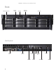
CHAPTER 1: Checking Out Your Gateway Server Front Hard drives (as many as 12) Hard drive tray LEDs Optical drive SMIL module bay (optional) Control panel Control panel VGA port USB ports (2) ID button Power button 2 Power LED ID LED NIC status LED System fault LED Reset button NMI button
www.gateway.
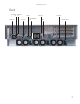
CHAPTER 1: Checking Out Your Gateway Server Interior 2 1 4 3 5 6 7 8 9 10 4 # Feature # Feature 1 System board 6 Front panel 2 Fan duct 7 Front panel VGA connector 3 System fans 8 SMIL module (optional) 4 SATA II/SAS backplane 9 Slimline DVD/CD-RW combo drive or DVD-RW drive 5 Hard drive bays 10 Riser card assembly
www.gateway.
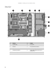
CHAPTER 1: Checking Out Your Gateway Server 6 # Feature # Feature 9 Serial port (J12) 27 Main power connector (J48) 10 PS/2 keyboard and mouse ports (J10) 28 Internal USB port for USB floppy (J59) 11 Rear dual USB Port (J6) 29 Power supply I2C connector (J55) 12 DIMM socket group for processor 3 (J14, J15, J16, J18) 30 System configuration jumper (J56) 13 Processor 3 (CPU3) socket 31 Floppy connector (J40) 14 Processor 1 (CPU1) socket 32 Battery (B1) 15 Processor power connect
www.gateway.
CHAPTER 1: Checking Out Your Gateway Server LED information See the following table for a description of this server’s LEDs and the information they provide: LED Name Function Location Color Description ID Aid in server identification Control panel and back of system board Yellow (front) Blue (back) On = Server identification enabled System Fault Visible fault warning Control panel Red Off = System normal Blinking = Non-critical system fault On = Critical system fault (system needs to be shu
www.gateway.com Getting Help In addition to your operating system’s documentation, you can use the following information resources to help you use your server. Server Companion DVD Use the Server Companion DVD to access file utilities, Windows Server 2003 drivers, and documentation for your server and its components. For instructions, see Using Your Server Companion DVD. Gateway Web site Gateway provides a variety of information on its Web site to help you use your server.
CHAPTER 1: Checking Out Your Gateway Server 10
CHAPTER2 Setting Up Your Server • • • • • Setting up the hardware Protecting from power source problems Starting your server Setting up the operating system Initial hardware settings 11
CHAPTER 2: Setting Up Your Server Setting up the hardware To make sure that your working environment is safe: • Use a clean, dry, flat, stable surface for your server. Allow at least 6 inches at the back of the server for cabling and air circulation. • Use the instructions on your server’s setup poster to set up your hardware. Caution Your server comes with 3-wire AC power cords fitted with the correct plug style for your region.
www.gateway.com Some surge protectors and uninterruptible power supplies include simple line-conditioning capabilities. Uninterruptible power supplies Use an uninterruptible power supply (UPS) to protect your server from data loss during a total power failure. A UPS uses a battery to keep your server running temporarily during a power failure and lets you save your work and shut down your server. You cannot run your server for an extended period of time while using only the UPS. To buy a UPS, visit www.
CHAPTER 2: Setting Up Your Server Turning off your server Every time you turn off your server, first shut down the operating system. You may lose data if you do not follow the correct procedure. To turn off the server: Caution The power button on the server does not turn off server AC power. To remove AC power from the server, you must unplug the AC power cords from the wall outlet or power source. The power cords are considered the disconnect device to the main (AC) power.
CHAPTER3 Maintaining Your Server • • • • • Caring for your server Preparing for system recovery System administration Identifying your server Updating the baseboard management controller firmware • Using your Server Companion DVD 15
CHAPTER 3: Maintaining Your Server Caring for your server To extend the life of your server: • Be careful not to bump or drop your server. • When transporting your server, we recommend that you put it in the original packaging materials. • Keep your server and magnetic media away from equipment that generates magnetic fields, such as unshielded speakers. • Avoid subjecting your server to extreme temperatures. Do not expose your server to heating ducts or other heat-generating objects.
www.gateway.com Cleaning the screen Caution The computer screen is made of specially coated glass and can be scratched or damaged by abrasive or ammonia-based glass cleaners. If your computer screen is an LCD display, use only a damp, soft cloth to clean it. Never spray water directly onto the screen. - OR If your computer screen is not a flat panel display, use a soft cloth dampened with glass cleaner to clean the screen. Never spray cleaner directly onto the screen.
CHAPTER 3: Maintaining Your Server Server security Locking the server To lock the server: 1 Remove the bezel lock keys from the inside of the bezel, then snap on the bezel. The handles must be installed for the bezel to snap on. 2 Insert the key into the lock and rotate it ¼ turn clockwise. To unlock it, rotate the key ¼ turn counter-clockwise. Using BIOS security passwords To prevent unauthorized use of the server, you can set server startup passwords.
www.gateway.
CHAPTER 3: Maintaining Your Server To install Acrobat Reader 7: • Click the link for Acrobat on the Documentation page. - OR Run Docs\Reader\app21279\Setup.exe from the Server Companion DVD. Installing drivers and programs You can install drivers and programs directly onto the server by using the Server Companion DVD. You can also extract drivers onto diskette from the DVD at any Windows workstation.
www.gateway.com Booting from the Server Companion DVD By booting from the SCDVD, you can repair applications and drivers or exit to the command prompt. Important Although the SCDVD is bootable, it does not include network operating system files and is not intended to restore your operating system. To boot from the SCDVD: 1 With your server turned on, insert the SCDVD into the DVD drive. 2 Restart your server. A message appears asking you to select an option. 3 Press any key to boot from the DVD.
CHAPTER 3: Maintaining Your Server 22
CHAPTER4 Installing Components • • • • • • • • • • • • • • • Preparing to install components Preventing static electricity discharge Opening the server case Closing the server case Installing and removing drives Installing memory Installing and removing PCI expansion cards Replacing system fans Replacing or adding a processor Replacing a power supply module Replacing the power distribution module Replacing the hot-swap backplane Replacing the CMOS battery Replacing the control panel Replacing the system bo
CHAPTER 4: Installing Components Preparing to install components Selecting a place to work Work on your server in an area that: • Is clean (avoid dusty areas). • Is a low-static environment (avoid carpeted areas). • Has a stable surface on which to set your server. • Has enough room to place all of your server parts. • Is near a grounded outlet so you can test your server after installation. • Is near a telephone (in case you need help from Gateway Customer Care).
www.gateway.com • Avoid static-causing surfaces such as carpeted floors, plastic, and packing foam. • Avoid working on the server when your work area is extremely humid. • Remove components from their antistatic bags only when you are ready to use them. Do • not lay components on the outside of antistatic bags because only the inside of the bags provide electrostatic protection. Always hold expansion cards by their edges or their metal mounting brackets.
CHAPTER 4: Installing Components 5 Remove the screw (1) at the front of the top cover, then press and hold the release button (2). Caution For correct cooling and air flow, always reinstall the top covers before you turn on the server. Operating the server without the covers in place will cause the server to overheat. Important The hard drive carriers shown in these illustrations may look different than the actual hard drive carriers in your server.
www.gateway.com Closing the server case To close the server case: 1 Make sure that all of the internal cables are arranged inside the case so they will not be pinched when you close the case. 2 Place the front top cover on the server, then slide it forward until it clicks into place. Important The hard drive carriers shown in these illustrations may look different than the actual hard drive carriers in your server.
CHAPTER 4: Installing Components Installing and removing drives Your server’s basic configuration includes one optical drive and as many as twelve SAS/SATA hot-swap hard drives. As you prepare to install drives, remember: • Before you install a drive, see the drive’s documentation for information on configuring the drive, setting drive jumpers, and attaching cables. • You may need to configure the drives you install using the BIOS Setup utility.
www.gateway.com 6 Move the optical drive to the right (3), then push the optical drive (4) out of the bay. 7 Unscrew the two screws (5) that secure the optical drive interface board to the optical drive, then remove the interface board. 8 Using the two screws you just removed, attach the optical drive interface board to the back of the new optical drive. 9 Insert the optical drive into the optical drive bay, aligning it with the clips on the right and left sides.
CHAPTER 4: Installing Components To remove and install a hot-swap hard drive: Caution Before you remove a failed drive, use the appropriate software and utilities installed on the server to stop all activity on the failed drive. Instructions for using the software are provided by the software manufacturer. Failure to do so may destroy the data on the drive. 1 Unlock the bezel (if necessary) and remove it by pulling it from the chassis. 2 Pull the drive release lever out. The drive release lever opens.
www.gateway.com Filling empty drive bays Empty drive bays in the server must be filled by drive trays with either hard drives or dummy hard drives installed. With the bezel removed, install the appropriate carrier, then replace the bezel by snapping it into place on the front of the server. Empty drive carriers for unused drive bays are included with your server. Installing memory Caution Use only DDR2-667 MHz compliant, 184-pin, SDRAM registered ECC, DIMM memory modules.
CHAPTER 4: Installing Components If you install two processors, refer to the following table: DIMM Processor DIMMA0 DIMMB0 DIMMA1 DIMMB1 Total Memory 4 Processor 0 - - 512 MB 512 MB 2 GB Processor 1 - - 512 MB 512 MB Processor 0 - - 1 GB 1 GB Processor 1 - - 1 GB 1 GB Processor 0 - - 2 GB 2 GB Processor 1 - - 2 GB 2 GB Processor 0 - - 4 GB 4 GB Processor 1 - - 4 GB 4 GB Processor 0 512 MB 512 MB 512 MB 512 MB Processor 1 512 MB 512 MB 512 MB 512 MB
www.gateway.
CHAPTER 4: Installing Components To install or replace memory: 1 Follow the instructions in “Preventing static electricity discharge” on page 24. Make sure that you turn off the server, then unplug the power cord(s) and all other cables connected to the server. 2 Follow the instructions in “Opening the server case” on page 25. 3 Pull the plastic tabs (1) away from the sides of the memory module slot. If you are replacing a memory module, lift the old memory module (2) out of the slot.
www.gateway.com 3 If you are replacing a card, disconnect any cables that are attached to the old card. 4 Push the riser card locking tabs (1) in the directions shown in the illustration. 5 Lift the riser card assembly out of the chassis (2) and place it on a clean, static-free surface.
CHAPTER 4: Installing Components 6 Press down and open the release lever (4) and flip open the card guide tab (5). 7 Remove the expansion card (6). If you are not replacing the card, install a slot cover (7) on the back of the riser card assembly. Caution Do not touch the contacts on the bottom part of the expansion card. Touching the contacts can cause electrostatic damage to the card. 8 If you are replacing the riser card, continue with the next step.
www.gateway.com 9 Press the tab (8) holding the riser card in the riser card assembly, then push the riser card in the direction shown (9) to unlock and remove it from the standoffs. Standoff 10 Insert the new riser card into the riser card assembly, then push it toward the back of the assembly. It should snap into place. 11 Insert the new PCI card into the riser card, making sure any connectors extend through the slot at the back of the assembly and that the card is fully seated in the riser card.
CHAPTER 4: Installing Components Replacing system fans This server contains five system fan groups seated in the fan cage. The fan cage is located inside the chassis and can hold as many as five groups of hot-swappable fans. When replacing a fan, it is not necessary to power off the server. These fans maintain the ideal temperature for the system board, backplane and disk drives. If one fan group fails, the speed of the other fan groups will increase.
www.gateway.com To replace the system fans and the fan cage: 1 Follow the instructions in “Preventing static electricity discharge” on page 24. 2 Follow the instructions in “Opening the server case” on page 25. 3 Remove the fan duct by lifting it out of the chassis. 4 Lift the retaining clip (1).
CHAPTER 4: Installing Components 5 Lift one side of the fan cage (2) and disengage the retention tab (3), then disconnect the fan power and fan tach cables from the system board and remove the fan cage from the chassis. 6 Insert the fans into the new fan cage. Important Make sure that the arrows on top of the fans indicating airflow point to the back of the chassis.
www.gateway.com Replacing or adding a processor Warning Processors and heat sinks may be hot if the computer has been running. Before replacing a processor or heat sink, let them cool for several minutes. Caution A heat sink must be installed on the processor. Installing a processor without a heat sink could damage the processor. The system board supports as many as four AMD® Opteron™ 8000 series processors with 3.0 GHz Hyper Transport Bus.
CHAPTER 4: Installing Components 6 Unlock the load lever (1) and lift it up, then open the load plate (2). This releases the processor (if you are replacing the processor), or prepares the socket for the installation of a new processor (if you are adding a processor). 7 Lift the processor (3) out of the socket (if necessary) and place it in a static-free bag or case for storage.
www.gateway.com 9 When the processor is oriented correctly and in place, press it firmly into the socket, rotate the load plate into place, and push down the load lever until it clicks into place. Caution The heatsink has Thermal Interface Material (TIM) located on the bottom of it. Use caution when you unpack the heatsink so you do not damage the TIM. If you are reusing the original heatsink, make sure that the TIM on the bottom of the heatsink is not damaged.
CHAPTER 4: Installing Components 3 Press the retaining clip (1) on the power supply to the left to release the power supply module (2) from the chassis. 4 Using the handle, pull the power supply module straight out of the server. It may take considerable force to remove. 5 Push the new power supply module into the server, with the retaining clip on the right, until it locks into place. 6 Reconnect the AC power cord for the new power supply module.
www.gateway.com 6 Loosen the thumbscrew (1), then lift the distribution module slightly and move it toward the front of the case (2) to release it from the three locking tabs. 7 Lift the power distribution board (3) out of the chassis. 8 Insert the new power distribution board into the chassis, then move it toward the back of the chassis to engage the three locking tabs. 9 Tighten the thumbscrew to secure the power distribution board in the chassis. 10 Reconnect the power cables.
CHAPTER 4: Installing Components Replacing the hot-swap backplane Caution The hot-swap backplane is not hot-swappable. Before removing or replacing the backplane, you must first turn off the server and all peripheral devices attached to the server, and remove the AC power cord(s) from the power supply or wall outlet. To replace the hot-swap backplane: 1 Follow the instructions in “Preventing static electricity discharge” on page 24.
www.gateway.com 10 Holding the new backplane by the edges only, align it with the locking tabs on the backplane bracket, then place it on the locking tabs (1) and slide it to the right until it click into place. Caution Make sure you do not pinch, bind, or damage any cables as you install the backplane. 11 Insert the backplane assembly into the chassis (2), then press down on the assembly until the locking tabs on the chassis engage the holes on the right and left sides of the bracket.
CHAPTER 4: Installing Components Replacing the CMOS battery Warning Danger of explosion if battery is incorrectly replaced. Replace only with the same or equivalent type recommended by the manufacturer. Dispose of or recycle used batteries by taking them to a hazardous waste facility. Follow all local regulations for correct battery disposal.
www.gateway.com Replacing the control panel Caution Your server must be operated with a control panel in place. To replace the control panel adapter card: 1 Follow the instructions in “Preventing static electricity discharge” on page 24. Make sure that you turn off the server, then unplug the power cord(s) and all other cables connected to the server. 2 Follow the instructions in “Opening the server case” on page 25. 3 Disconnect all cables from the control panel.
CHAPTER 4: Installing Components 8 Loosen the two thumbscrews (1) that secure the system board to the server. 2 2 2 2 2 1 1 9 Slide the system board toward the back of the server until it is free of the five retaining standoffs (2), then lift the board from the chassis. 10 Place the old system board in a static-free bag for storage.
CHAPTER5 Using the BIOS Setup Utility • • • • • Opening the BIOS Setup utility Updating the BIOS Recovering the BIOS Resetting the BIOS Updating and recovering the BMC 51
CHAPTER 5: Using the BIOS Setup Utility Opening the BIOS Setup utility The BIOS Setup utility stores basic settings for your server. These settings include basic hardware configuration, resource settings, and password security. These settings are stored and saved even when the power is off. Caution The options in the BIOS Setup utility have been set at the factory for optimal performance. Changes to these settings will affect the performance of your server.
www.gateway.com Recovering the BIOS If you encounter a problem while you are updating the BIOS, such as a power outage, the BIOS update may not be successful. If the system continues to try to boot from the new, corrupted BIOS, you can manually recover the old BIOS so you can try another update. Important This method does not work if the keyboard is connected through the KVM switch.
CHAPTER 5: Using the BIOS Setup Utility 12 Follow the instructions in “Closing the server case” on page 27. 13 Plug in the AC power cords and turn on the server, then verify that the recovery was successful. Resetting the BIOS You can use two methods to clear all BIOS Setup settings and return them to the factory defaults: • Press the power and reset buttons on the front of the server. • Move the Clear CMOS jumper on the system board.
www.gateway.com 9 Turn off the server, then disconnect the power cords and all other cables connected to the server. 10 Follow the instructions in “Opening the server case” on page 25. 11 Place the jumper back onto pins 1-2. 12 Follow the instructions in “Closing the server case” on page 27. Resetting BIOS passwords To reset BIOS passwords, you must either reset and clear all BIOS settings, or use the Clear Password jumper.
CHAPTER 5: Using the BIOS Setup Utility Updating and recovering the BMC Updating the BMC firmware To update the BMC firmware: 1 Download the BMC firmware zip file from support.gateway.com. 2 Read the release notes for the firmware update. 3 Follow the instructions on the Web site or in the readme.txt file in the downloaded zip file to update the firmware. 4 When the BMC update is complete, reboot your server.
CHAPTER6 Troubleshooting • • • • • Telephone support Tutoring and training Safety guidelines Error messages Troubleshooting 57
CHAPTER 6: Troubleshooting Telephone support Before calling Gateway Customer Care If you have a technical problem with your server, follow these recommendations before contacting Gateway Customer Care: • Make sure that your server is connected correctly to a grounded AC outlet that is supplying power. • If a peripheral device, such as a keyboard or mouse, does not appear to work, make sure that all cables are plugged in securely and plugged into the correct port or jack.
www.gateway.com Tutoring and training Gateway's Customer Care professionals cannot provide hardware and software training. Instead, Gateway recommends the following training resources. Resource Service description For more information Gateway Learning Libraries A variety of courses and tutorials are available on CD. Select from several easy-to-use learning libraries. www.gateway.
CHAPTER 6: Troubleshooting Drive Not Ready The BIOS was unable to access the drive because it indicated it was not ready for data transfer. This is often reported by drives when no media is present. A: Drive Error The BIOS attempted to configure the A: drive during POST, but was unable to correctly configure the device. This may be due to a bad cable or faulty diskette drive. Insert BOOT diskette in A: The BIOS attempted to boot from the A: drive, but could not find a correct boot diskette.
www.gateway.com S.M.A.R.T. Capable but Command Failed The BIOS tried to send a S.M.A.R.T. message to a hard disk, but the command transaction failed. This message can be reported by an ATAPI device using the S.M.A.R.T. error reporting standard. S.M.A.R.T. failure messages may indicate the need to replace the hard disk. S.M.A.R.T. Command Failed The BIOS tried to send a S.M.A.R.T. message to a hard disk, but the command transaction failed. This message can be reported by an ATAPI device using the S.M.A.R.T.
CHAPTER 6: Troubleshooting PCI I/O conflict A PCI adapter generated an I/O resource conflict when configured by BIOS POST. PCI ROM conflict A PCI adapter generated an I/O resource conflict when configured by BIOS POST. PCI IRQ conflict A PCI adapter generated an I/O resource conflict when configured by BIOS POST. PCI IRQ routing table error BIOS POST (DIM code) found a PCI device in the system but was unable to figure out how to route an IRQ to the device.
www.gateway.com Troubleshooting First steps Warning To avoid bodily injury, do not attempt to troubleshoot your server problem if: - The power cords or plugs are damaged - Liquid has been spilled into your server - Your server was dropped - The case was damaged Instead, unplug your server and contact a qualified computer technician.
CHAPTER 6: Troubleshooting Beep codes Whenever a recoverable error occurs during the power-on self-test (POST), the BIOS displays an error message that describes the problem. The BIOS also sounds a beep code (one long tone followed by two short tones) during POST if the video configuration fails (a faulty video controller) or if an expansion card is not functioning correctly. One short beep indicates the BIOS will boot the operating system. No error found.
www.gateway.com Diagnostic LEDs This system board provides a set of eight diagnostic (Port 80) LEDs. If you are troubleshooting your system, these LEDs can help you determine where errors are taking place. If you are experiencing problems with your server, open the case and check these LEDs (CR22 to CR29) on the system board, then check the tables on the following pages to determine the problem.
CHAPTER 6: Troubleshooting In determining the code, Off = 0 and On = 1. Based on this, you can determine the corresponding hex code. Then, by checking “POST code checkpoints” on page 66, “Bootblock initialization code checkpoints” on page 68, “Bootblock recovery code checkpoints” on page 69, “DIM code checkpoints” on page 70, and “ACPI runtime checkpoints” on page 70, you can find out where an error is taking place.
www.gateway.com Check point Description 2A Initialize different devices through DIM. See “DIM code checkpoints” on page 70 for more information. 2C Initialize different devices. Detects and initializes the video adapter installed in the system that has optional ROMs. 2E Initialize all the output devices. 31 Allocate memory for ADM module and uncompress it. Give control to ADM module for initialization. Initialize language and font modules for ADM. Activate ADM module.
CHAPTER 6: Troubleshooting Check point Description A2 Take care of runtime image preparation for different BIOS modules. Fill the free area in F000h segment with 0FFh. Initializes the Microsoft® IRQ Routing Table. Prepares the runtime language module. Disables the system configuration display, if needed. A4 Initialize runtime language module. A7 Display the system configuration screen, if enabled. Initialize the CPUs before boot, including the programming of the MTRRs.
www.gateway.com Check point Description D9 Store the Uncompressed pointer for future use in PMM. Copying Main BIOS into memory. Leaves all RAM below 1 MB Read-Write, including E000 and F000 shadow areas, but closing SMRAM. DA Restore CPUID value back into register. Give control to BIOS POST (ExecutePOSTKernel). See “POST code checkpoints” on page 66 for more information.
CHAPTER 6: Troubleshooting DIM code checkpoints The Device Initialization Manager (DIM) gets control at various times during BIOS POST to initialize different system buses. The following table describes the main checkpoints where the DIM module is accessed. Checkpoint Description 2A Initialize different buses and perform the following functions: ■ Reset, Detect, and Disable (function 0) — Disables all device nodes, PCI devices, and PnP ISA cards. It also assigns PCI bus numbers.
www.gateway.com • Make sure that the drive is configured correctly by following the instructions in the drive’s documentation. • Turn off your server, then remove the drive and push it in again to make sure the drive is seated correctly. For instructions, see “Removing and installing an optical drive” on page 28. Your optical drive tray does not open • Press a straightened paper clip wire into the optical drive’s manual eject hole. The drive tray opens.
CHAPTER 6: Troubleshooting Internet You cannot connect to the Internet • Make sure that your account with your Internet Service Provider (ISP) is set up correctly. Contact your ISP technical support for help. Keyboard Liquid has been spilled into the keyboard • If you spilled liquid in the keyboard, turn off your server and unplug the keyboard. Clean the keyboard and turn it upside down to drain it. Let the keyboard dry before using it again.
www.gateway.com Power You press the power button, but the server does not turn on • If the power button LED is green, the server is turned on, but you may not be seeing an image on the monitor. For monitor troubleshooting, see “Monitor” on page 72. • If your server is plugged into a surge protector or UPS, make sure that the surge protector or UPS is connected securely to an electrical outlet, turned on, and working correctly.
CHAPTER 6: Troubleshooting 74
APPENDIXA Server Specifications • • • • • System specifications System board specifications Environmental specifications Electronic specifications Additional specifications 75
APPENDIX A: Server Specifications System specifications Case size 5.12 × 17.56 × 27.56 inches (13.0 × 44.6 × 70.0 cm) Weight Minimum - 79.37 lbs (36 Kg) (no bezel, power supplies, hard drives, optical drive, fans, cables, and so on) Maximum - 99.21 lbs (45 Kg) (±0.
www.gateway.com LAN ■ ■ ■ ACPI nVIDIA MCP55 and IO55 Four onboard 10/100/1000 network interface Supports teaming, load-balancing, failover, TOE, and jumbo frame ACPI 2.0b compliance Supports: ■ S0 ■ S1 ■ S5 Environmental specifications The following specifications identify maximum environmental conditions. At no time should the server run under conditions which violate these specifications.
APPENDIX A: Server Specifications Address Range (hex) Amount Function 0E0000h to 0EFFFFh 2 MB Extended system BIOS FC000000h to FFFFFFFFh 64 MB PCI memory space Interrupts Important If you disable an IDE controller to free the interrupt for that controller, you must physically unplug the IDE cable from the system board. Simply disabling the drive by configuring the BIOS option does not make the interrupt available.
www.gateway.com Pin Signal Name 4 +5 V 5 Ground 6 +5 V 7 Ground 8 Power good 9 Stand by +5 V 10 +12 V 11 +12 V 12 +3.3 V 13 +3.
APPENDIX A: Server Specifications VGA connector Pin Signal Name 1 Red 2 Green 3 Blue 4 No connection 5 GND 6 GND 7 +5 V 8 GND 9 +5 V 10 GND 11 No connection 12 SDA 13 HSYNC (horizontal sync) 14 VSYNC (vertical sync) 15 SCL Serial port connector Pin Signal Name Description 1 DCD Data Carrier Detect 2 RXDATA Receive Data 3 TXDATA Transmit Data 4 DTR Data Terminal Ready 5 GND Ground 6 DSR Data Set Ready 7 RTS Request To Send 8 CTS Clear To Send 9 RI
www.gateway.com Pin Signal Name 3 GND 4 +5 V 5 Keyboard (or mouse) clock 6 NC External USB connectors Pin Signal Name 1 +5 V 2 USBn Data- 3 USBn Data+ 4 GND I2C (SMBus) connector Pin Signal Name 1 I2C SCL 2 I2C SDA 3 I2C Alert 4 Ground 5 +3.3 V Additional specifications For more information about your server, such as memory size, hard drive size, and processor type, visit Gateway’s Support page at support.gateway.com.
APPENDIX A: Server Specifications 82
APPENDIXB BIOS Settings 83
APPENDIX B: BIOS Settings If you ever need to restore your BIOS settings, such as after a system board change, a record of the settings will make the process much easier. You can print this appendix, then record your custom BIOS settings on the printout. Only settings which can be changed are listed. For a complete list of viewable BIOS settings, run the BIOS Setup utility. To view all BIOS settings: 1 Restart your server. 2 Press F2 at any time after you see the LEDs on your keyboard flash or turn off.
www.gateway.com BIOS menu BIOS submenu Setting Value ACPI 2.
APPENDIX B: BIOS Settings BIOS menu BIOS submenu Setting Value MCP55 SATA 0 Secondary (auto-detected) Selects IDE Configuration sub-menu. MCP55 SATA 1 Primary (auto-detected) Selects IDE Configuration sub-menu. MCP55 SATA 1 Secondary (auto-detected) Selects IDE Configuration sub-menu. MCP55 SATA 2 Primary (auto-detected) Selects IDE Configuration sub-menu. MCP55 SATA 2 Secondary (auto-detected) Selects IDE Configuration sub-menu.
www.gateway.com BIOS menu BIOS submenu Setting Value USB Configuration USB Devices Enabled (List of USB devices detected by BIOS) Legacy USB Support Disabled Enabled Auto USB 2.
APPENDIX B: BIOS Settings BIOS menu BIOS submenu Setting Value Quick Boot Disabled Enabled Quiet Boot Disabled Enabled Bootup Num-Lock On Off POST Error Pause Disabled Enabled Security Supervisor Password (Installed/Not installed) User Password (Installed/Not installed) Change Supervisor Password (Set or clear Supervisor password) User Access Level No Access View Only Limited Full Access Change User Password (Set or clear User password) Password Check Disabled Enabled Boot Sector Virus Prot
www.gateway.
APPENDIX B: BIOS Settings This second level submenu is accessed from the submenu indicated in the first column.
APPENDIXC Legal Information 91
APPENDIX C: Legal Information Regulatory compliance statements United States of America Federal Communications Commission (FCC) Unintentional emitter per FCC Part 15 FCC Part 15 Class A Statement The server is designated as complying with Class A requirements if it bares the following text on the rating label: This device complies with Part 15 of the FCC Rules. Operation is subject to the following two conditions: (1) This device may not cause harmful interference.
www.gateway.com For unique identification of the product configuration, please submit the 10-digit serial number found on the product to the responsible party. This device complies with Part 15 of the FCC Rules. Operation of this product is subject to the following two conditions: (1) this device may not cause harmful interference, and (2) this device must accept any interference received, including interference that may cause undesired operation.
APPENDIX C: Legal Information Environmental information The product you have purchased contains extracted natural resources that have been used in the manufacturing process. This product may contain substances known to be hazardous to the environment or to human health.
APPENDIXD Legal Information 95
APPENDIX D: Legal Information Important safety information Warning Always follow these instructions to help guard against personal injury and damage to your Gateway system. Your Gateway system is designed and tested to meet the latest standards for safety of information technology equipment. However, to ensure safe use of this product, it is important that the safety instructions marked on the product and in the documentation are followed.
Index Numerics 5.
Index removing 29 troubleshooting 71 heat sink installing 41 help telephone support 58 tutoring 59 hot-swap backplane 7, 46 backplane, SATA II/SAS 7 hard drives 2, 29 power supply 43 hot-swap drives installing 29 location 2 I IDE connectors 5 drive configuration 28 indicators 2, 13 information LED 8, 72 installing add-in card 34 backplane 46 battery 48 card 34 drives 28 expansion cards 34 hard drive 29 heat sink 41 hot-swap drive 29 memory 31 mezzanine board 47 PCI expansion card 34 PCI riser assembly 34
www.gateway.
Index 100
A MAN E-9722R USR GDE R3 06/07