GATEWAY CONVERTIBLE NOTEBOOK SERVICEGUIDE ®
Contents Replacing convertible notebook components . . . . . . . . . . . . . . . . . . . . . . . . . 1 Identifying the convertible notebook model . . . . . . . . . . . . . . . . . . . . . . . . . . . . . . . . . . 2 Identifying components . . . . . . . . . . . . . . . . . . . . . . . . . . . . . . . . . . . . . . . . . . . . . . . . . . . . 3 Preparing your work space . . . . . . . . . . . . . . . . . . . . . . . . . . . . . . . . . . . . . . . . . . . . . . . . . 3 Preventing static electricity discharge .
Contents ii
Replacing convertible notebook components • • • • • • • • • • • • • • • • • • • • • • • • • • • • • Identifying the convertible notebook model Identifying components Preparing your work space Preventing static electricity discharge Preparing the convertible notebook Replacing a bay module Adding or replacing memory modules Replacing the cooling assembly Replacing the processor Replacing the IEEE 802.
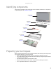
Replacing convertible notebook components Important The color of your convertible notebook may vary from the pictures in this service guide. Important This service guide is not intended to be provided to individual users or consumers. It cannot be provided to anyone other than an authorized service provider. Important For information on the convertible notebook’s general maintenance, technical support, safety notices, and regulatory notices, see the convertible notebook’s user guide.
www.gateway.com Identifying components Use this chart to identify the main components of the convertible notebook. For a complete list of replaceable parts, see “Contents” on page i.
Replacing convertible notebook components • When removing components that are attached to the convertible notebook by a cable, unplug the cable before removing the screws, when possible, to avoid damaging the cable. • As you remove components and screws, lay them toward the rear of your work surface • (behind the convertible notebook) or far enough to the side that your arms do not accidentally brush them onto the floor.
www.gateway.com Preparing the convertible notebook To prepare the convertible notebook for maintenance: Make sure that the disc drive is empty. 1 2 3 4 5 Turn off the convertible notebook. Make sure the LCD panel is in notebook mode, then close the LCD panel. Disconnect your convertible notebook from the optional port replicator. Disconnect the AC adapter, modem cable, and network cable, if connected to the convertible notebook.
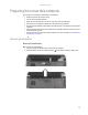
Replacing convertible notebook components Removing the optional secondary battery To remove the optional secondary battery: 1 Remove the modular bay lock screw (if one is present), then slide and hold the module bay latch. The battery may move out slightly. Modular bay lock screw 2 Slide the battery out.
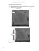
www.gateway.com Replacing a bay module Tools you need to complete this task: Phillips #0 screwdriver Screws removed during this task: 1 black 2.5*8.0 (Optional bay module security screw) Security screw (optional) Modular bay latch Modular bay To replace a bay module: 1 If you are removing a drive, make sure that there is no disc in it. 2 Complete the steps in “Preparing the convertible notebook” on page 5. 3 Turn the convertible notebook over so the bottom is facing up.
Replacing convertible notebook components 4 Remove the modular bay lock screw (if one is present), then slide and hold the module bay latch. The drive may move out slightly. Modular bay lock screw 5 Slide the drive out. 6 Firmly push the new drive straight into the bay until the latch clicks into place. 7 Replace the module bay lock screw.
www.gateway.com Adding or replacing memory modules Important Use only memory modules designed for this Gateway convertible notebook. Tools you need to complete this task: Phillips #0 screwdriver Memory bay To add or replace memory modules: 1 Complete the steps in “Preparing the convertible notebook” on page 5. 2 Loosen the screws that secure the memory cover. (These screws cannot be removed.) Screw Screw Screw Screw Screw Screw 3 Remove the memory bay cover.
Replacing convertible notebook components 4 If you are removing a memory module, gently press outward on the clip at each end of the module until the module tilts upward. Clip Clip 5 Pull the module out of the slot. 6 Hold the new or replacement module at a 30-degree angle and press it into the empty memory slot. This module is keyed so it can only be inserted in one direction. If the module does not fit, make sure that the notch in the module lines up with the tab in the memory bay.
www.gateway.com Replacing the cooling assembly Tools you need to complete this task: v Phillips #0 screwdriver Additional materials you need to complete this task: • X-23-7762 thermal grease Cooling assembly bay To replace the cooling assembly: 1 Complete the steps in “Preparing the convertible notebook” on page 5. 2 Loosen the screws that secure the cooling assembly bay cover. (These screws cannot be removed.
Replacing convertible notebook components 3 Remove the cooling assembly bay cover. Be careful not to break off the tabs located on the bottom of the cover. If the cover does not remove easily, wiggle the cover to loosen it. 4 Loosen the four screws that secure the cooling assembly to the system board. (These screws cannot be removed.) Use the numbers stamped in the metal next to each screw and loosen the screws in reverse numerical order (start with 4, then 3, then 2, then 1).
www.gateway.com 7 At the same time as you lift, move the cooling assembly away from the side of the convertible notebook. 8 Remove any thermal grease residue from the processor using a soft cloth and isopropyl alcohol. 9 Place new thermal grease on the processor. Use only enough to cover the CPU die. 10 Make sure thermal pads are placed between the cooling assembly and other components as shown.
Replacing convertible notebook components Replacing the processor Tools you need to complete this task: v Phillips #0 screwdriver Flat-blade driver Additional materials you need to complete this task: • X-23-7762 thermal grease To replace the processor: 1 Complete the steps in “Preparing the convertible notebook” on page 5. 2 Remove the cooling assembly by following the steps in “Replacing the cooling assembly” on page 11.
www.gateway.com 4 Remove the old processor from the system board. 5 Install the new processor onto the system board making sure that Pin 1 on the processor (indicated by the silk-screened arrow on the corner of the processor) aligns with Pin 1 on the processor socket (indicated by the absence of a pin hole in the processor socket), then use a flat-blade screwdriver to turn the processor lock screw 1/4-turn clockwise.
Replacing convertible notebook components Replacing the IEEE 802.11 wireless card Tools you need to complete this task: Phillips #0 screwdriver Screws removed during this task: 2 chrome 2.0*3.0 (IEEE 802.11 wireless card) Select models only Wireless bay To replace the IEEE 802.11 wireless card: 1 Complete the steps in “Preparing the convertible notebook” on page 5.
www.gateway.com 2 Loosen the screw that secures the wireless cover. (This screw cannot be removed.) Screw 3 Remove the wireless bay cover. Be careful not to break off the tabs located on the bottom of the cover. If the cover does not remove easily, wiggle the cover to loosen it. 4 Unplug the antenna cables. Note which color cable is connected to each of the connectors. Important The number of antenna cables varies by the type of wireless network used by the convertible notebook. IEEE 802.
Replacing convertible notebook components 6 If the wireless card is held by clips, press outward on the clip at each side of the card until the card tilts upward. 0 Clip Clip -ORIf the wireless card is held by screws, remove the screws.
www.gateway.com 7 Pull the card out of the slot. 8 Hold the new card at a 30-degree angle and press it into the empty slot. This card is keyed so it can only be inserted in one direction. If the card does not fit, make sure that the notch in the card lines up with the tab in the card slot. 9 Move the antenna cables out of the way. 10 Press the card down until it clicks into place. -ORPress the card down, then replace the screws removed in Step 6. 11 Reattach the antenna cables to the connectors.
Replacing convertible notebook components Replacing the CMOS battery Important Use only CMOS batteries designed for this Gateway convertible notebook. Tools you need to complete this task: v Flat-blade driver - OR - Scribe or non-marring tool Phillips #0 screwdriver Screws removed during this task: 2 chrome 2.0*3.0 (IEEE 802.11 wireless card) Select models only To replace the CMOS battery: 1 Complete the steps in “Preparing the convertible notebook” on page 5.
www.gateway.com Replacing the hard drive Tools you need to complete this task: Phillips #0 screwdriver Screws removed during this task: 1 chrome 2.5*5.0 (Hard drive) 4 chrome 3.0*0.5+3.5I (Hard drive bracket) Hard drive To replace the hard drive: 1 Complete the steps in “Preparing the convertible notebook” on page 5.
Replacing convertible notebook components 2 Loosen the screws that secure the hard drive bay cover. (These screws cannot be removed.) Screw Screw 3 Remove the hard drive bay cover. Be careful not to break off the tabs located on the bottom of the cover. If the cover does not remove easily, wiggle the cover to loosen it.
www.gateway.com 4 Remove the hard drive screw.
Replacing convertible notebook components 5 Slide the old hard drive kit out of the convertible notebook. 6 Remove the four screws that secure the hard drive to the hard drive kit bracket. Screw Screw Screw Screw 7 Insert the new drive into the bracket, label side up, so the screw holes line up. 8 Replace the four screws that were removed in Step 6.
www.gateway.com 9 Slide the new hard drive into your convertible notebook, then replace the screw that was removed in Step 4. 10 Replace the hard drive bay cover, then tighten the cover screws.
Replacing convertible notebook components Replacing the hinge covers Tools you need to complete this task: v Flat-blade driver - OR - Scribe or non-marring tool To replace the hinge covers: 1 Complete the steps in “Preparing the convertible notebook” on page 5. 2 Turn the convertible notebook over so the top is facing up. 3 Insert the small flat-blade screwdriver or non-marring tool under the bottom of the back hinge cover, then carefully pry it up.
www.gateway.com Replacing the keyboard cover Tools you need to complete this task: v Flat-blade driver - OR - Scribe or non-marring tool To replace the keyboard cover: Complete the steps in “Preparing the convertible notebook” on page 5. 1 2 3 4 Turn the convertible notebook over so the top is facing up. Open the LCD panel to the fully open position. Insert the small flat-blade screwdriver under the bottom of the keyboard cover between the PAUSE and INSERT keys and gently pry it up.
Replacing convertible notebook components Replacing the keyboard Tools you need to complete this task: v Flat-blade driver - OR - Scribe or non-marring tool Phillips #0 screwdriver Screws removed during this task: 2 black 2.5*8.0 (Keyboard) To replace the keyboard: 1 Complete the steps in “Preparing the convertible notebook” on page 5. 2 Remove the two bottom keyboard screws. Tip The screw holes are marked with a K.
www.gateway.com 4 Lift the back edge of the keyboard slightly, then slowly slide it toward the LCD panel to release the keyboard retaining tabs located on the front edge of the keyboard. 5 Carefully rotate the keyboard toward you so it lies keys-down on top of your convertible notebook. Be careful not to damage the LCD panel. 6 Swing the black keyboard connector clip up, then lift the cable out of the connector. Be careful not to touch or damage any other components.
Replacing convertible notebook components 9 Insert the tabs on the front edge of the keyboard into the slots under the palm rest. You may need to press down on the keyboard keys along the front edge of the keyboard to seat the retaining tabs into their corresponding slots. 10 Gently press the keyboard down until it is flat all the way across. The keyboard should easily fall into place. Be careful to not damage the LCD panel.
www.gateway.com Replacing the inverter Tools you need to complete this task: v Flat-blade driver - OR - Scribe or non-marring tool Phillips #0 screwdriver Screws removed during this task: 4 or 8 black 2.5*5.0 (LCD panel front) 1 chrome 2.5*2.5 (Inverter) To replace the inverter: 1 Complete the steps in “Preparing the convertible notebook” on page 5. 2 Remove the keyboard cover by following the steps in “Replacing the keyboard cover” on page 27. 3 Open the LCD panel to the fully open position.
Replacing convertible notebook components 5 Remove the screws from the front of the LCD panel assembly. Important The number of screws varies by convertible notebook model. Screw Screw Screw Screw Screw Screw Screw Screw 6 Carefully separate the front and back of the LCD panel assembly. 7 Disconnect the connectors from the inverter. 8 Remove the screw that connects the inverter to the front of the LCD panel assembly.
www.gateway.com 9 Align the new inverter with the screw hole, replace the screw that was removed in Step 8, then reconnect the cables. 10 Press the LCD panel front and back together. Press the two halves together in several places until they click in place. You should find no loose spots or spots where the two halves do not meet. 11 Replace the LCD panel assembly screws removed in Step 5. 12 Replace the inserts removed in Step 4. Caution The larger rubber inserts go across the top of the panel.
Replacing convertible notebook components Replacing the power button board Tools you need to complete this task: v Flat-blade driver - OR - Scribe or non-marring tool Phillips #0 screwdriver Screws removed during this task: 4 or 8 black 2.5*5.0 (LCD panel front) 2 chrome 2.5*6.0 (Power button board) To replace the power button board: 1 Complete the steps in “Preparing the convertible notebook” on page 5.
www.gateway.com 5 Remove the screws from the front of the LCD panel assembly. Important The number of screws varies by convertible notebook model. Screw Screw Screw Screw Screw Screw Screw Screw 6 Carefully separate the front and back of the LCD panel assembly. 7 Disconnect the power button cable from the power button board.
Replacing convertible notebook components 8 Remove the two screws that connect the power button board to the front of the LCD panel assembly, then remove the board. Screw Screw 9 Install the new power button board. 10 Replace the screws that were removed in Step 8, then reconnect the cable. 11 Press the LCD panel front and back together. Press the two halves together in several places until they click in place. You should find no loose spots or spots where the two halves do not meet.
www.gateway.com Replacing the tablet button board Tools you need to complete this task: v Flat-blade driver - OR - Scribe or non-marring tool Phillips #0 screwdriver Screws removed during this task: 4 or 8 black 2.5*5.0 (LCD panel front) 2 chrome 2.5*6.0 (Tablet button board) To replace the tablet button board: 1 Complete the steps in “Preparing the convertible notebook” on page 5. 2 Remove the keyboard cover by following the steps in “Replacing the keyboard cover” on page 27.
Replacing convertible notebook components 5 Remove the screws from the front of the LCD panel assembly. Important The number of screws varies by convertible notebook model. Screw Screw Screw Screw Screw Screw Screw Screw 6 Carefully separate the front and back of the LCD panel assembly. 7 Disconnect the tablet button cable from the tablet button board.
www.gateway.com 8 Remove the two screws that connect the tablet button board to the front of the LCD panel assembly, then remove the board. Screw Screw 9 Install the new tablet button board. 10 Replace the screws that were removed in Step 8, then reconnect the cable. 11 Press the LCD panel front and back together. Press the two halves together in several places until they click in place. You should find no loose spots or spots where the two halves do not meet.
Replacing convertible notebook components Replacing the LCD assembly Tools you need to complete this task: v Flat-blade driver - OR - Scribe or non-marring tool Phillips #0 screwdriver Screws removed during this task: 4 or 6 black 2.5*8.0 (LCD hinge to notebook) To replace the LCD assembly: 1 Complete the steps in “Preparing the convertible notebook” on page 5.
www.gateway.com 7 Remove the keyboard cover by following the steps in “Replacing the keyboard cover” on page 27. 8 Detach the three cables from the system board. 9 Grasp the plastic tab carefully and pull to unplug the LCD video cable from the convertible notebook. Make sure you grasp the tab, not the cable. Caution The connector is fragile.
Replacing convertible notebook components 12 Lift the LCD panel assembly up and away from the convertible notebook. The LCD panel assembly is now completely detached from the convertible notebook. 13 Place the new LCD panel assembly onto the convertible notebook, then replace the two hinge screws removed in Step 11. 14 Slide the antenna cables through the retaining clips, under the system board, then into the wireless card area. 15 16 17 18 Plug the LCD video cable into the convertible notebook.
www.gateway.com Replacing the LCD panel hinge Tools you need to complete this task: v Flat-blade driver - OR - Scribe or non-marring tool Phillips #0 screwdriver Screws removed during this task: 4 or 6 black 2.5*8.0 (LCD hinge to notebook) 4 or 8 black 2.5*5.0 (LCD panel front) 4 black 2.5*3.5 (LCD hinge to LCD panel) To replace the LCD panel hinge: 1 Complete the steps in “Preparing the convertible notebook” on page 5.
Replacing convertible notebook components 8 Remove the screws from the front of the LCD panel assembly. Important The number of screws varies by convertible notebook model. Screw Screw Screw Screw Screw Screw Screw Screw 9 Carefully separate the front and back of the LCD panel assembly. 10 Carefully pull the wiring out of the hinge. Tip Start by pulling the wire that has the smallest connector out of the hinge. Then proceed to the wire that has the next biggest connector and so on.
www.gateway.com 11 Remove the four screws that secure the old hinge to the LCD panel assembly. Screws Screws 12 Replace the new hinge onto the LCD panel assembly. 13 Replace the screws removed in Step 11. 14 Feed the wiring back into the hinge. Tip Start by feeding the wire that has the largest connector into the hinge. Then proceed to the wire that has the next smallest connector and so on. 15 Replace the screws that were removed in Step 8, then reconnect the cable.
Replacing convertible notebook components Replacing the LCD panel Tools you need to complete this task: v Flat-blade driver - OR - Scribe or non-marring tool Phillips #0 screwdriver Screws removed during this task: 4 or 6 black 2.5*8.0 (LCD hinge to notebook) 4 or 8 black 2.5*5.0 (LCD panel front) 4 black 2.5*8.0 (LCD panel) To replace the LCD panel: 1 Complete the steps in “Preparing the convertible notebook” on page 5.
www.gateway.com 9 Remove the screws connecting the LCD panel to the LCD lid. Screw Screw Screw 10 11 12 13 Screw Remove the old LCD panel from the LCD lid. Place the new LCD panel into the LCD lid. Replace the screws removed in Step 9. Feed the wiring back into the hinge. Tip Start by feeding the wire that has the largest connector into the hinge. Then proceed to the wire that has the next smallest connector and so on.
Replacing convertible notebook components Replacing the LCD assembly lid Tools you need to complete this task: v Flat-blade driver - OR - Scribe or non-marring tool Phillips #0 screwdriver Screws removed during this task: 4 or 6 black 2.5*8.0 (LCD hinge to notebook) 2 chrome 2.5*6.0 (Power button board) 4 or 8 black 2.5*5.0 (LCD panel front) 2 chrome 2.5*6.0 (Tablet button board) 1 chrome 2.5*2.5 (Inverter) 4 black 2.5*3.5 (LCD hinge to LCD panel) 4 black 2.5*8.
www.gateway.com 9 Remove the LCD panel hinge by following the instructions in “Replacing the LCD panel hinge” on page 43. 10 Remove the screws connecting the LCD panel to the old LCD lid. Screw Screw Screw 11 12 13 14 Screw Remove the LCD panel from the old LCD lid. Place the LCD panel into the new LCD lid. Replace the screws removed in Step 10. Replace the LCD panel hinge by following the instructions in “Replacing the LCD panel hinge” on page 43.
Replacing convertible notebook components Replacing the palm rest Tools you need to complete this task: v Flat-blade driver - OR - Scribe or non-marring tool Phillips #0 screwdriver Screws removed during this task: 1 black 2.5*8.0 (Optional bay module security screw) 4 or 6 black 2.5*8.0 (LCD hinge to notebook) 3 chrome 2.0-0.4*2.0 (palm rest-modular drive bay) 1 chrome 2.5*5.0 (Hard drive) 14-16 black 2.5*8.0 (palm rest-bottom) 1 black 2.5*8.0 (palm rest-top) 2 black 2.5*8.
www.gateway.com 9 Remove the screws shown in the following picture. Note the location of the screw types and sizes. Some models may have fewer screws than shown or screws in a slightly different location. Important The number of screws varies by convertible notebook model. Screws Screws Screws Screws 10 Turn the convertible notebook over so the top is facing up. 11 Flip the black touchpad connector clip up, then remove the cable. Be careful not to touch or damage any other components.
Replacing convertible notebook components 13 Remove the screw from the top of the palm rest. Screw 14 Starting on the right side, lift the palm rest assembly up and away from the convertible notebook. Be careful when pulling the palm rest assembly away from the bottom near the docking port.
www.gateway.com Replacing the fingerprint reader Tools you need to complete this task: v Flat-blade driver - OR - Scribe or non-marring tool Phillips #0 screwdriver Screws removed during this task: 1 black 2.5*8.0 (Optional bay module security screw) 4 or 6 black 2.5*8.0 (LCD hinge to notebook) 3 chrome 2.0-0.4*2.0 (palm rest-modular drive bay) 1 chrome 2.5*5.0 (Hard drive) 14-16 black 2.5*8.0 (palm rest-bottom) 1 black 2.5*8.0 (palm rest-top) 2 black 2.5*8.0 (Keyboard) 2 chrome 2.0*5.
Replacing convertible notebook components 10 Disconnect the fingerprint reader cable. 11 Remove the screws from the metal clips covering the ends of the fingerprint reader. Screw Screw 12 Lift the metal clips off of the fingerprint reader. Clip Clip 13 Remove the fingerprint reader from the convertible notebook. 14 Place the new fingerprint reader into the convertible notebook in the same orientation as the old reader.
www.gateway.com 17 18 19 20 Replace the palm rest by following the steps in “Replacing the palm rest” on page 50. Replace the LCD assembly by following the steps in “Replacing the LCD assembly” on page 40. Replace the keyboard by following the steps in “Replacing the keyboard” on page 28. Replace the keyboard cover by following the steps in “Replacing the keyboard cover” on page 27. 21 Replace the hinge covers by following the steps in “Replacing the hinge covers” on page 26.
Replacing convertible notebook components Replacing the Bluetooth module Tools you need to complete this task: v Flat-blade driver - OR - Scribe or non-marring tool Phillips #0 screwdriver Screws removed during this task: 1 black 2.5*8.0 (Optional bay module security screw) 4 or 6 black 2.5*8.0 (LCD hinge to notebook) 3 chrome 2.0-0.4*2.0 (palm rest-modular drive bay) 1 chrome 2.5*5.0 (Hard drive) 14-16 black 2.5*8.0 (palm rest-bottom) 2 black 2.5*8.0 (Keyboard) 2 chrome 2.0*5.
www.gateway.com 10 Disconnect the cable from the old Bluetooth module, then slide the module from the convertible notebook. 11 12 13 14 15 16 Slide the new Bluetooth module into the convertible notebook. Connect the cable to the new Bluetooth module. Replace the palm rest by following the steps in “Replacing the palm rest” on page 50. Replace the LCD assembly by following the steps in “Replacing the LCD assembly” on page 40.
Replacing convertible notebook components Replacing the system board Tools you need to complete this task: v Flat-blade driver - OR - Phillips #0 screwdriver Scribe or non-marring tool 5.0 mm hex nutdriver Additional materials you need to complete this task: • X-23-7762 thermal grease Screws removed during this task: 1 black 2.5*8.0 (Optional bay module security screw) 1 chrome 2.5*5.0 (Hard drive) 14-16 black 2.5*8.0 (palm rest-bottom) 1 black 2.5*8.0 (palm rest-top) 2 chrome 2.0*3.0 (IEEE 802.
www.gateway.com 4 Remove the cooling assembly by following the instructions in “Replacing the cooling assembly” on page 11. 5 If your new system board does not include a processor, remove the processor from the old system board and install it on the new system board by following the instructions in “Replacing the processor” on page 14. 6 Remove the optional IEEE 802.11 wireless card from the old system board and install it on the new system board by following the instructions in “Replacing the IEEE 802.
Replacing convertible notebook components 15 Unplug the speakers from the system board (one connector). Speaker connector 16 Unplug the Bluetooth module from the system board (one connector).
www.gateway.com 17 Remove the system board screws. Important The number of screws varies by convertible notebook model. Screw Screw Screw Screw 18 Carefully remove the system board. 19 Turn the system board over so the bottom is facing up, then remove the modem from the old system board and install it on the new system board by following the instructions in “Replacing the modem” on page 63.
Replacing convertible notebook components 26 27 28 29 Replace the palm rest by following the steps in “Replacing the palm rest” on page 50. Replace the LCD assembly by following the steps in “Replacing the LCD assembly” on page 40. Replace the keyboard by following the steps in “Replacing the keyboard” on page 28. Replace the keyboard cover by following the steps in “Replacing the keyboard cover” on page 27. 30 Replace the hinge covers by following the steps in “Replacing the hinge covers” on page 26.
www.gateway.com Replacing the modem Tools you need to complete this task: v Flat-blade driver - OR - Phillips #0 screwdriver Scribe or non-marring tool 5.0 mm hex nutdriver Screws removed during this task: 1 black 2.5*8.0 (Optional bay module security screw) 4 or 6 black 2.5*8.0 (LCD hinge to notebook) 3 chrome 2.0-0.4*2.0 (palm rest-modular drive bay) 1 chrome 2.5*5.0 (Hard drive) 14-16 black 2.5*8.0 (palm rest-bottom) 1 black 2.5*8.0 (palm rest-top) 2 black 2.5*8.0 (Keyboard) 2 chrome 2.
Replacing convertible notebook components 7 8 9 10 11 Remove the keyboard by following the steps in “Replacing the keyboard” on page 28. Remove the LCD assembly by following the steps in “Replacing the LCD assembly” on page 40. Remove the palm rest by following the steps in “Replacing the palm rest” on page 50. Remove the system board by following the steps in “Replacing the system board” on page 58.
www.gateway.com 13 Turn the modem over, then unplug the modem cable from the modem. 14 15 16 17 18 19 Install the new modem on the system board. Replace the system board following the steps in “Replacing the system board” on page 58. Replace the palm rest by following the steps in “Replacing the palm rest” on page 50. Replace the LCD assembly by following the steps in “Replacing the LCD assembly” on page 40. Replace the keyboard by following the steps in “Replacing the keyboard” on page 28.
Replacing convertible notebook components Replacing the TPM module (select models) Important If the TPM module is not located in the wireless bay, use the procedure found in “Replacing the TPM module (select models)” on page 67 to replace the TPM module. Tools you need to complete this task: v Flat-blade driver - OR - Scribe or non-marring tool Phillips #0 screwdriver Screws removed during this task: 2 black 2.0*2.
www.gateway.com Replacing the TPM module (select models) Important If the TPM module is located in the wireless bay, use the procedure found in “Replacing the TPM module (select models)” on page 66 to replace the TPM module. Tools you need to complete this task: v Flat-blade driver - OR - Phillips #0 screwdriver Scribe or non-marring tool 5.0 mm hex nutdriver Screws removed during this task: 1 black 2.5*8.0 (Optional bay module security screw) 4 or 6 black 2.5*8.
Replacing convertible notebook components 5 Remove the hinge covers by following the steps in “Replacing the hinge covers” on page 26. 6 Remove the keyboard cover by following the steps in “Replacing the keyboard cover” on page 27. 7 8 9 10 11 Remove the keyboard by following the steps in “Replacing the keyboard” on page 28. Remove the LCD assembly by following the steps in “Replacing the LCD assembly” on page 40. Remove the palm rest by following the steps in “Replacing the palm rest” on page 50.
MAN VIPER / C / SR SVC GDE R2 6/07