
User manual
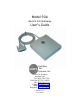

GateWay Fax Systems, inc. Model 90si Secure Fax Gateway User's Guide
www.gwfs.com, 877-951-9800, info@gwfs.com help line: 877-951-9814 page 6
RESET Button When pressed it causes a hardware and software reset. While the light is blink-
ing, self-tests are executed. When the light is on steady, the unit is ready to
operate.
FAULT Indicator (Red) It illuminates for 90 seconds following an error condition and is off during
normal operation.
POWER Indicator (Green) When illuminated, power is applied and self-tests were successful.
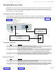
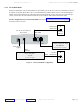
STE "Red" Data Cable
(required)
This serial data cable is terminated with an RS-232 (25 Pin) connector that
goes to the "Red" Data Port on the back of your secure telephone or crypto.
FAX Connector
(required)
This connector is used for all congurations. It connects to the "Line" or "L"
jack on your COTS or computer-based fax.
STE Connector
(optional)
Used only for the 1-Line, Dual-Mode conguration where it connects to the
PSTN jack on the Secure Phone. It is not used for the Secure Only or 2-Line
Dual-Mode congurations.
TEL LINE Connector
(optional)
Used only for Dual-Mode congurations (1-Line Dual-Mode or 2-Line Dual-
Mode) where it connects to a commercial 2-wire loop telephone line.
EXT 5VDC SUPPLY
(required)
This connects to the supplied 110-220VAC auto-sensing power supply.
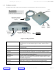
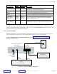
13 Looking at your 90si
The gures below indicate the location and functions of the 90si buttons, indicators and connectors.
Old -vs- New 90si:
• Old 90si has DIP switches on bottom.
• New Async-Capable 90si does not.
FAX
(required)
90si Phone
Connections
TEL LINE
(optional)
STE
(optional)
5VDC Power
Connector
(required)
"Red" Data Connector
RD-232, DB-25 pin
(required)
Power
Indicator
(Green)
Reset
Button
Figure x - Looking at your 90si
Fault
Indicator
(Red)