
Brochure

Gastite Division, Titeflex Corporation
1116 Vaughn Parkway / Portland, TN 37148
800.662.0208 / www.gastite.com / gastite@gastite.com
66
April 2015
Section 4: Installation Practices
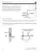
4.8.3 Installation
a) e regulator shall be installed in an accessible location with an approved shut-off valve and drip leg on the inlet side and a
union (if required by code) on the outlet side so that it may be inspected, maintained and serviced if repair or replacement
is required. e regulator must be installed with gas flow as indicated by the arrow on the casting.
b) Shut-off valves should be opened and closed slowly. A rapidly opened or closed valve can shock the regulator causing
abnormal behavior.
c) e regulator is suitable for multi-poise mounting. When using a vent-limiting orifice however, the regulator must be
mounted in a horizontal upright position.
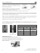
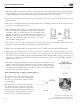
d) e vent-limiting orifice (Fig. 4-87) is a fail-safe device that permits
free air movement above the diaphragm during normal operation. In
the unlikely event of a diaphragm rupture, the vent limiting orifice
will limit gas escapement to 1.0 CFH natural gas at 2 PSI and 0.65
CFH LP at 2 PSI. Both values are below the ANSI standard of 2.5
CFH. Note: e vent-limiting orifice does not allow gas to escape to
the environment during operation.
e) Do not leak test the vent orifice with liquid leak test solution. is action will contaminate the internal check ball
mechanism or plug the breathing hole resulting in erratic regulator performance
f) When using a vent-limiting orifice, the maximum inlet pressure is 2 PSI for Propane and 5 PSI for Natural Gas.
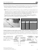
g) When using a vent line, the line must be at least the same size as the regulator vent connection for all runs up to 30 feet
and shall be increased one pipe size over its entirety for every additional 30 feet that the vent runs. Vent lines may be
constructed of any approved fuel gas piping, including FlashShield™ CSST. e vent shall be designed to prevent entry of
water, insects or other foreign materials that could cause blockage of the line. Do not vent to appliance flue, pilot light or
building exhaust system.
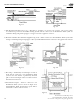
h) e regulators supplied by Gastite Division have a temperature range limit of -40 to 240
degrees F. e lower temperature limit and rust proof construction design enables the
regulator to be used for outdoor installations. To minimize the potential for moisture
condensation and freezing problems in or around the vent port, the vent-limiting orifice
must be removed for outdoor installations.
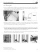
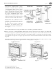
Outdoor Mounting Options: (Figures 4-88 through 4-90)
e regulator may be mounted upside down with
the open vent port facing down. Consideration
must be taken to ensure there is adequate clearance
for snow buildup.
e regulator may be mounted horizontally, with a
vent tube installed in the venting port. e end of
the tube must be facing downward, and should be
designed to prevent water and foreign material from
causing a blockage. Another alternative is an outdoor
plastic vent protector designed for the regulator.
Fig. 4-87
Fig. 4-88
Fig. 4-89 Fig. 4-90