
Brochure

Gastite Division, Titeflex Corporation
1116 Vaughn Parkway / Portland, TN 37148
800.662.0208 / www.gastite.com / gastite@gastite.com
55
April 2015
Section 4: Installation Practices
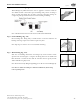
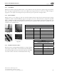
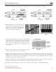
a) At concealed support points and points of penetration 2 to 3 inches from any edge of a stud, joist plate, etc., listed 1/4
striker plates are required to provide protection throughout the area of penetration (Fig. 4-51 and 4-52).
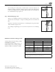
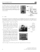
b) When multiple runs are located between the
same two studs such as manifold runs or meter
bank runs, a 6" x 17" panel type striker plate
may be used as an alternate to individual striker
plates for each tubing run (Fig. 4-54).
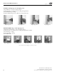
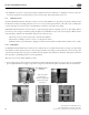
c) When installed inside insulated exterior walls, tubing shall be
routed between the face of the insulation and the interior wall
surface (Fig. 4-55). If rigid insulation is used, enough space
must be provided for movement of the tubing (see Section
4.4) or heavy wall conduit must run over the length of the
restrained area.
d) At points of penetration greater than 3 inches from any edge
of stud, joist, plate, etc., no protection is required.
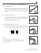
e) Tubing routed horizontally through structural members shall be protected from puncture threats with the appropriate
shielding material (Figure 4-51 and 4-52). At penetration points, listed plates of the appropriate size shall be utilized
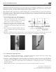
Tubing between constraints that are less than 24 inches apart and meeting the criteria requiring full striker plates, shall be
additionally protected by Steel Conduit (Fig. 4-53).
f) FlashShield™ CSST greater than 1" nominal diameter installed within a concealed hollow wall cavity of 2"x4" construction
shall be protected along the entire concealed run length with Steel Conduit (see Section 4.4.2).
g) e width of installed striker plates shall be at least 1.5 times the outside diameter of the FlashShield™ CSST.
Fig. 4-51
Fig. 4-52
Fig. 4-54Fig. 4-53
Fig. 4-55