
Brochure


Gastite Division, Titeflex Corporation
1116 Vaughn Parkway / Portland, TN 37148
800.662.0208 / www.gastite.com / gastite@gastite.com
33
April 2015
Section 3: System Configuration
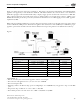
3.2.9 Example 8 - Summation Method for Parallel System – 7"WC – Hybrid
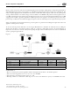
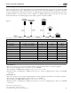
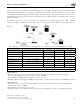
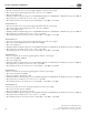
Figure 3-16 below shows the same house as Example 6. e piping is arranged in parallel fashion, with individual CSST
appliance runs supplied by a main distribution manifold. e main trunk line (“A”) from the meter to the distribution
manifold is rigid pipe rather than CSST. e utility company’s supply pressure (downstream of the meter) is 7"WC. e
utility company advises that the specific gravity of the gas delivered will be 0.60 and the energy content is 1 CFH = 1000
BTUH. e allowable pressure drop across the system has been determined to be 2.0"WC (supply pressure 7"WC - appliance
requirement 5"WC).
When using the “Summation Method” for gas pipe sizing, the sum of the pressure losses through each section of pipe should
result in a minimum 5"WC pressure delivered to the appliance inlet. (Pressures less than 5"WC may be sufficient for proper
appliance operation but should be reviewed with the manufacturer’s input rating and the local administrative authority).
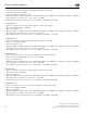
Table 3-9
Section Description Load Delivered by Section Section Length Tube Size
“A” – Rigid Trunk 221 CFH = 221,000 BTUH 45 feet 3/4" Rigid
“B” – Furnace 80 CFH = 80,000 BTUH 15 feet 1/2" CSST
“C” – Water Heater 36 CFH = 36,000 BTUH 10 feet 3/8" CSST
“D” – Range 52 CFH = 52,000 BTUH 20 feet 1/2" CSST
“E” – Dryer/BBQ Trunk 53 CFH = 53,000 BTUH 20 feet 1/2" CSST
“F” – Dryer 28 CFH = 28,000 BTUH 5 feet 3/8" CSST
“G” – BBQ 25 CFH = 25,000 BTUH 5 feet 3/8" CSST
SIZING RUN “A”
• Run “A” is sized by the total load of all appliances and the section length
• e total load of all appliances is 80 + 36 + 52 + 28 + 25 = 221CFH
• e section length is 45ft
• Referring to Table 7-24 (Pressure drop per foot for Rigid Pipe): for a 225CFH load, 3/4" pipe has a drop of 0.021"WC
per ft
• e pressure drop over Run “A” is: 0.021" x 45ft = 0.945"WC
• e available pressure at the end of run “A” is 7"WC - 0.945"WC = 6.055"WC
Fig. 3-16