
Brochure

Gastite Division, Titeflex Corporation
1116 Vaughn Parkway / Portland, TN 37148
800.662.0208 / www.gastite.com / gastite@gastite.com
15
April 2015
Section 3: System Configuration
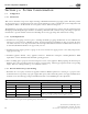
3.1.4 Determining System Layout
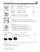
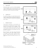
a) Series Systems
A series layout (Fig 3-1) is the most common arrangement
utilized for rigid pipe systems for low pressure. ese usually
consist of a main run (header) with tees branching off to each
appliance. In a traditional series system, the service pressure
down stream of the meter is typically less than 1/2 PSI.
b) Parallel Systems
In a parallel system (Fig. 3-2) a main run from the meter
supplies a central distribution manifold. e appliances are
serviced by individual runs from the manifold. e manifold
station is best located close to the greatest load, typically the
boiler or furnace.
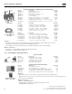
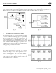
c) Dual Pressure System
A dual pressure system (Fig. 3-3, 3-4) incorporates two
operating pressures downstream from the meter. e first
pressure, set by the service regulator at the meter, is usually
2 PSI but can be higher or lower depending on code
restrictions and gas company policy. is part of the system
is sized separately and ends at the pounds-to-inches regulator
inlet. Tables 4-7, 4-8 and 4-9 show maximum loads vs. inlet
pressures to the regulator.
e second pressure, at the outlet of the pounds-to-inches
regulator, is under 1/2 PSI; usually 8"WC for natural gas
and 11"WC for propane regulators supplied by Gastite®.
Generally, a parallel system requires a higher total footage of
smaller diameter tubing and fewer fittings compared to a series
layout.
Fig. 3-1
Fig. 3-2
Fig. 3-3
Fig. 3-4
Multi-Unit Apartment Building