
Brochure

Gastite Division, Titeflex Corporation
1116 Vaughn Parkway / Portland, TN 37148
800.662.0208 / www.gastite.com / gastite@gastite.com
14
April 2015
Section 3: System Configuration
S . S C
3.1 Configuration
3.1.1 Introduction
is section is intended to help in the design and sizing of FlashShield™ CSST fuel gas piping systems. e form -printed
on the previous page is to aid in keeping track of the system requirements as well as organizing the system configuration and
sizing numbers. Refer to the Gastite web site (www.gastite.com) for additional sizing tools.
e FlashShield™ gas piping system is required to be tested, listed, and installed in accordance with the Standard For Fuel
Gas Piping Systems Using Corrugated Stainless Steel Tubing, ANSI LC1. is standard, among other things, requires the
manufacturer to provide installation instructions including the necessary pipe sizing tables and methods of sizing.
3.1.2 System Requirements
• Determine the local piping restrictions prior to installing the flexible gas piping. Confirm that the local administrative
authority has accepted the use of flexible gas piping. Corrugated Stainless Steel Tubing has been accepted by all major
code bodies, but local or state adoption of these codes often lags behind. Check with the local administrative authority or
an authorized FlashShield distributor for approval in your area.
• Determine metered (supply) pressure. A gauge can be used to measure the supply pressure or the utility will provide a
supply pressure rating.
• Determine appliance demand. Every appliance will have a manufacture’s nameplate containing BTUH or CFH
requirements as well as minimum and maximum operating pressures.
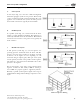
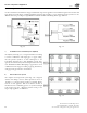
• Refer to building plans or prepare a sketch showing the location of each appliance. When preparing this sketch keep in
mind the safest, easiest, and shortest distance locations to run the piping. Label the pipe segments and the corresponding
lengths. Take note of fittings needed e.g. tees, manifolds, reducers.
3.1.3 Reference Data for Proper System Sizing
• Determine the total capacity needed for all appliances. CFH or BTUH equivalents for natural gas or propane can be
obtained from the local gas utility or propane supplier. e capacity tables within this guide or other approved CSST tables
should be used to determine pipe sizing for FlashShield needed to meet BTUH input load requirements.
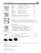
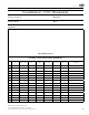
Table 3-1 Reference Data for Proper System Sizing
Pressure Conversion Factors Fuel Gas Information
1/4 PSI = 6.921"WC = (approx. 7"WC) Natural Gas Propane
1/2 PSI = 13.842"WC = (approx. 14"WC) BTU per Cubic Foot = 1000 2516
1 PSI = 27.684"WC = (approx. 28"WC) Specific Gravity = 0.6 1.52
2 PSI = 55.368"WC = (approx. 56"WC)
Note: “Pressure Drop Curves are expressed in terms of Cubic Feet per Hour
(CFH). To determine the CFH for Natural Gas, divide the BTU load by 1000.
To determine the CFH for Propane, divide the BTU load by 2516.
5 PSI = 138.42"WC = (approx. 140"WC)
Refer to Section 7.0 for gases with a specific gravity other than 0.60.