Metallically-Shielded CSST D E S I G N A N D I N S TA L L AT I O N G U I D E Commercial I Industrial I Residential April 2015 www.gastite.
FlashShield™ Installer Information and Updates 1) W hen using the XR3 fitting, proper removal of the outer jacket layer on FlashShield CSST is required for the electrical continuity of the system. Using the Jacket Stripping Tool is the easiest way to achieve the correct FlashShield end-prep condition and to ensure electrical continuity of the system. Proper FlashShield End Prep Proper XR3 Bushing Placement 2) L icensed Installers Only.
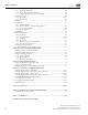
Table of Contents April 2015 Section 1.0 Introduction 1.1 General User Warnings.....................................................................................................1 1.2 Limitations of the Guidelines...........................................................................................3 1.3 Standards, Listings and Codes..........................................................................................3 Section 2.0 System Descriptions & Components 2.1 System Descriptions........
Table of Contents April 2015 4.3.6 Outdoor..................................................................................................................53 4.3.7 Fire Rated Constructions..........................................................................................53 4.3.8 Routing Through Masonry Material..........................................................................53 4.3.9 Clearance From the Underside of a Roof Deck....................................................
Section 1: Introduction April 2015 Section 1.0 Introduction 1.1 General User Warnings The installation of FlashShield™ Flexible Gas Piping must be performed by a qualified installer who has successfully completed the FlashShield™ training program. FlashShield™ certifications are valid for 3 years. Certification training is available through qualified distributors, and at www.gastite.com.
Section 1: Introduction 1.1 April 2015 General User Warnings (continued) A FlashShield™ Flexible Gas Piping system offers advantages over other gas delivery systems because of its wall dimensions and corrugated design. In contrast to rigid steel pipe, FlashShield™ does not require intermediate joints in most installations because the tubing is capable of being installed in one continuous run, reducing not only the total number of joints, but also the potential for leaks at joints.
Section 1: Introduction 1.2 April 2015 Limitations of the Guidelines This document is intended to aid the professional gas installer in the design, installation and testing of fuel gas piping systems using corrugated stainless steel tubing (CSST) for residential housing, commercial and industrial buildings. It would be impossible for this guideline to anticipate and cover every possible variation in building configurations, construction styles, appliance loads and code restrictions.
Section 2: System Components April 2015 Section 2.0 System Descriptions & Components 2.1 FlashShield™ System Description a) The FlashShield™ Flexible Gas Piping System has been tested in accordance with the American National Standard for Fuel Gas Systems Using Corrugated Stainless Steel Tubing, ANSI LC1. This standard lists performance requirements for certification of CSST systems for use with all recognized fuel gases, including Natural Gas and Propane.
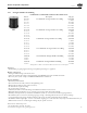
Section 2: System Components April 2015 2.2 Corrugated Stainless Steel Tubing 2.2.1 Corrugated Stainless Steel Tubing Part No. FLASHSHIELD™ CORRUGATED STAINLESS STEEL TUBING (CSST) Description Pkg. Qty.
Section 2: System Components 2.2.2 April 2015 Fittings XR3 SERIES STRAIGHT FITTING (ADAPTER/NUT/BUSHING) Part No. Description Pkg. Qty.
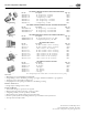
Section 2: System Components 2.2.2 April 2015 Fittings Termination Fitting With Square Flange Termination Fitting No Flange Term Bracket Fitting XR3 SERIES TERMINATION FITTING (FLANGE/ADAPTER/NUT/BUSHING) Part No. Description Pkg. Qty. XR3TRM-8-12 1/2" Term. Fitting-Square Flange – 1/2" NPT 12/Box XR3TRM-11-12 3/4" Term. Fitting-Square Flange – 3/4" NPT 12/Box XR3TRM-16-6 1" Term. Fitting-Square Flange – 1" NPT 6/Box XR3TRM-20-6 1-1/4" Term.
Section 2: System Components 2.2.3 April 2015 Manifolds Cast Manifolds Part No.
Section 2: System Components 2.2.5 April 2015 Mounting Hardware Termination Bracket Manifold Bracket Part No. LBRACE-1-20 MBRACE-1-10 MBRACE-3-10 GLC1 GLC1-PANEL MOUNTING HARDWARE Description Term.
Section 2: System Components 2.2.7 April 2015 Strike Protection Part No. TFM204-100 TFM201-50 TFM203-50 TFM205-25 TFM210-10 TFM211-25 TFM212-25 SIL-TAPE SIL-TAPE-B Striker Plates Steel Conduit Coil & Cut Length Application PROTECTION DEVICES – STRIKER PLATES & SILICONE TAPE Description Pkg. Qty.
Section 2: System Components 2.2.9 April 2015 FlashShield™ Accessories Tubing Cutters Part No. GTCUTTER-SM GTCUTTER-LG GTCUTTER-LG2 GTBLADE-SM-5 GTBLADE-LG-5 GTBLADE-LG2-5 TUBING CUTTERS AND ACCESSORIES Description Cutter with flat rollers – 3/8" – 1" FlashShield™ CSST Cutter with flat rollers – Up to 1-1/2" FlashShield™ CSST Cutter with flat rollers – Up to 2" FlashShield™ CSST Replacement blade for GTCUTTER-SM Replacement blade for GTCUTTER-LG Replacement blade for GTCUTTER-LG2 Pkg. Qty. 1 Ea.
Section 2: System Components April 2015 2.2.12 Regulators Maxitrol Regulators Maxitrol Regulators with OPD OARA Regulators Part No.
April 2015 FlashShield™ CSST Worksheet Project / Location: Drawn By: Contact Phone: Date: Description System Description System Data and Requirements Name of Run Supply Pressure Length of Run (Lbs. or In.) (Ft.) Load of Run (CFH) Press. Drop (Lbs. or In.) Tube Diameter Delivery Press. (Size or In.) (Lbs. or In.) Comments A B C D E F G H I J K L M N O To be copied: For Planning and Design of the FlashShield Piping System. Visit www.gastite.com for a downloadable version of this worksheet.
Section 3: System Configuration April 2015 Section 3.0 System Configuration 3.1 Configuration 3.1.1 Introduction This section is intended to help in the design and sizing of FlashShield™ CSST fuel gas piping systems. The form -printed on the previous page is to aid in keeping track of the system requirements as well as organizing the system configuration and sizing numbers. Refer to the Gastite web site (www.gastite.com) for additional sizing tools.
Section 3: System Configuration 3.1.4 Determining System Layout a) Series Systems April 2015 A series layout (Fig 3-1) is the most common arrangement utilized for rigid pipe systems for low pressure. These usually consist of a main run (header) with tees branching off to each appliance. In a traditional series system, the service pressure down stream of the meter is typically less than 1/2 PSI. b) Parallel Systems Fig. 3-1 In a parallel system (Fig.
Section 3: System Configuration d) April 2015 Multiple Manifold Systems For those installations in which the energy load demand is large or the appliances are installed throughout the structure with long distances from the meter, a multiple manifold system may be used (Fig. 3-5, 3-6). Elevated pressure systems are a safe, efficient method of providing for larger BTUH load demands while maintaining smaller pipe diameters. Fig. 3-5 e) Fig.
Section 3: System Configuration 3.1.5 April 2015 Allowable Pressure Drop With respect to gas pipe sizing, the intent of all model codes is to ensure that there is sufficient gas volume and pressure supplied to the appliance for proper operation. Language from the International Fuel Gas Code clearly illustrates this point.
Section 3: System Configuration April 2015 Sizing for a Hybrid System (one that includes both rigid pipe and CSST) is accomplished by using the longest run method to determine the appropriate pipe size for a given load and run length. Each segment of the piping system uses the appropriate sizing table for that particular piping material. This procedure is shown in Examples 6 & 7.
Section 3: System Configuration 3.2.2 April 2015 Example 1 - Series System – 6"WC Figure 3-9 below shows a typical single-family house installation with five (5) appliances. The piping is arranged in series with a main run branching at the appliances. The utility company’s supply pressure (downstream of the meter) is 6"WC. The utility company advises that the specific gravity of the gas delivered will be 0.60 and the energy content is 1 CFH = 1000 BTUH.
Section 3: System Configuration April 2015 SIZING RUN “C” • Run “C” is sized by the total load of all supplied appliances and the run length from the meter to the furthest appliance • The total load of all appliances is 52 + 28 + 25 = 105CFH • The run length to the BBQ (furthest appliance) is 40 + 5 + 10 + 10 + 5 = 70ft • Referring to Table 7-2 (1.
Section 3: System Configuration 3.2.3 April 2015 Example 2 - Parallel System – 6"WC Figure 3-10 below shows the same house as Example 1. The piping is arranged in parallel fashion, with individual CSST appliance runs supplied by a main distribution manifold. The utility company’s supply pressure (downstream of the meter) is 6"WC. The utility company advises that the specific gravity of the gas delivered will be 0.60 and the energy content is 1 CFH = 1000 BTUH.
Section 3: System Configuration April 2015 SIZING RUN “C” • Run “C” is sized by the load of the supplied appliance and the run length to the supplied appliance • The load of the water heater is 36CFH • The run length to the water heater is 45 + 10 = 55ft • Referring to Table 7-2 (1.
Section 3: System Configuration 3.2.4 April 2015 Example 3 - Parallel System – 12-14"WC Figure 3-11 below shows the same house and piping system as Example 2. The piping is arranged in parallel fashion, with individual CSST appliance runs supplied by a main distribution manifold. The utility company’s supply pressure (downstream of the meter) is 12-14"WC. The utility company advises that the specific gravity of the gas delivered will be 0.60 and the energy content is 1 CFH = 1000 BTUH.
Section 3: System Configuration April 2015 SIZING RUN “C” • Run “C” is sized by the load of the supplied appliance and the run length to the supplied appliance • The load of the water heater is 36CFH • The run length to the water heater is 45 + 10 = 55ft • Referring to Table 7-8 (6.
Section 3: System Configuration 3.2.5 April 2015 Example 4 - Dual Pressure System – 2 PSI Trunk and 8"WC Appliance Runs Figure 3-12 below shows the same house and similar piping system as Example 3. The piping is arranged in parallel fashion, with individual CSST appliance runs supplied by a main distribution manifold. A regulator is mounted at the manifold. The utility company’s supply pressure (downstream of the meter) is 2 PSI.
Section 3: System Configuration April 2015 SIZING RUN “C” • Run “C” is sized by the load of the supplied appliance and the run length to the supplied appliance • The load of the water heater is 36CFH • The run length to the water heater is 10ft • Referring to Table 7-5 (3.
Section 3: System Configuration 3.2.6 April 2015 Example 5 - Multiple Manifold System Figure 3-13 below shows the same house and similar piping system as Example 4. The piping is arranged in parallel fashion, with individual CSST appliance runs supplied by two distribution manifolds. Regulators are mounted at each manifold. The utility company’s supply pressure (downstream of the meter) is 2 PSI. The utility company advises that the specific gravity of the gas delivered will be 0.
Section 3: System Configuration April 2015 SIZING RUN “E” • Run “E” is sized by the load of all supplied appliances and the run length from the meter to the farthest regulator • The total load of all appliances is 28 + 25 = 53CFH • The run length to the farthest regulator is 45 + 20 = 65ft • Referring to Table 7-10 (2 PSI with a 1 PSI drop): for a 70-ft run, 3/8" CSST has a capacity over 53CFH (97 actual) NOTE: Gastite® recommends that trunk lines be 1/2" minimum.
Section 3: System Configuration 3.2.7 April 2015 Example 6 - Series System – 7"WC - Hybrid Figure 3-14 below shows a typical single-family house retrofit installation with five (5) appliances, 2 of which are added onto an existing black pipe system. The piping is arranged in series with a main run branching at the appliances. The utility company’s supply pressure (downstream of the meter) is 7"WC. The utility company advises that the specific gravity of the gas delivered will be 0.
Section 3: System Configuration April 2015 SIZING RUN “C” • Run “C” is sized by the total load of all supplied appliances and the run length from the meter to the furthest appliance • The total load of all appliances is 52 + 28 + 25 = 105CFH • The run length to the BBQ (furthest appliance) is 40 + 5 + 10 + 10 + 5 = 70ft • Referring to Table 7-23 (Rigid pipe 0.
Section 3: System Configuration 3.2.8 April 2015 Example 7 - Parallel System – 7"WC – Hybrid Figure 3-15 below shows the same house and similar piping system as Example 2. The piping is arranged in parallel fashion, with individual CSST appliance runs supplied by a main distribution manifold. The main trunk line (“A”) from the meter to the distribution manifold is rigid pipe rather than CSST. The utility company’s supply pressure (downstream of the meter) is 7"WC.
Section 3: System Configuration April 2015 SIZING RUN “C” • Run “C” is sized by the load of the supplied appliance and the run length from the meter to the supplied appliance • The load of the water heater is 36CFH • The run length to the water heater is 45 + 10 = 55ft • Referring to Table 7-4 (2.
Section 3: System Configuration 3.2.9 April 2015 Example 8 - Summation Method for Parallel System – 7"WC – Hybrid Figure 3-16 below shows the same house as Example 6. The piping is arranged in parallel fashion, with individual CSST appliance runs supplied by a main distribution manifold. The main trunk line (“A”) from the meter to the distribution manifold is rigid pipe rather than CSST. The utility company’s supply pressure (downstream of the meter) is 7"WC.
Section 3: System Configuration April 2015 SIZING RUN “B” • Run “B” is sized by the load of the supplied appliance and the section length • The load of the furnace is 80CFH • The section length to the furnace is 15ft • Referring to Table 7-21 (Pressure drop per foot for FlashShield™ CSST): for a 80CFH load, 1/2" CSST has a drop of 0.037"WC / ft • The pressure drop over Run “B” is: 0.037" x 15ft = 0.555"WC • The available pressure at the end of run “B” is 6.055"WC - 0.555"WC = 5.
Section 3: System Configuration April 2015 3.2.10 Example 9: Summation Method for Series System – 6"WC Figure 3-17 below shows the same house and piping system as Example 1. The piping is arranged in series with a main run branching at the appliances. The utility company’s supply pressure (downstream of the meter) is 6"WC. The utility company advises that the specific gravity of the gas delivered will be 0.60 and the energy content is 1 CFH = 1000 BTUH.
Section 3: System Configuration April 2015 SIZING RUN “B” • Run “B” is sized by the total load of all supplied appliances and the section length • The total load of the supplied appliances is 36 + 52 + 28 + 25 = 141CFH • The section length is 5ft • Referring to Table 7-21 (Pressure drop per foot for FlashShield™ CSST): for a 150CFH load, 1" CSST has a drop of 0.006"WC / ft • The pressure drop over Run “B” is: 0.006" x 5ft = 0.030"WC • The available pressure at the end of run “B” is 5.440"WC - 0.
Section 3: System Configuration April 2015 3.2.10 Example 9: Summation Method for Series System – 6"WC (Continued) SIZING RUN “H” • Run “H” is sized by the load of the supplied appliance and the section length • The load of the range is 52CFH • The section length to the range is 10ft • Referring to Table 7-21 (Pressure drop per foot for FlashShield™ CSST): for a 60CFH load, 3/4" CSST has a drop of 0.004"WC / ft • The pressure drop over Run “H” is: 0.004" x 10ft = 0.
Section 3: System Configuration April 2015 3.2.11 Example 10 - Commercial Elevated Pressure Series System – 2 PSI Figure 3-18 below shows a typical commercial rooftop installation with four (4) appliances. The piping is arranged in series with a main run branching at the appliances. The utility company’s supply pressure (downstream of the meter) is 2 PSI. The utility company advises that the specific gravity of the gas delivered will be 0.60 and the energy content is 1 CFH = 1000 BTUH.
Section 3: System Configuration April 2015 SIZING RUN “B” • Run “B” is sized by the total load of all supplied appliances and the run length from the meter to the furthest appliance • The total load of the supplied appliances is 250 + 250 + 500 = 1000CFH • The run length to the Air Handler (furthest appliance) is 15 + 15 + 15 + 15 = 60ft • Referring to Table 7-10 (2 PSI line pressure, 1 PSI pressure drop): for a 60ft run, 1" CSST has a capacity over 1000CFH (actual: 1213) SIZING RUN “C” • Run “C” is sized
Section 3: System Configuration April 2015 3.2.12 Example 11 - Commercial Hybrid System – 7"WC Figure 3-19 below shows a multi-level apartment building. The piping is arranged in vertical parallel fashion, with individual CSST appliance runs supplied by distribution manifolds. The main trunk line (“A”-“D”) from the meter to the distribution manifolds is rigid pipe rather than CSST. The utility company’s supply pressure (downstream of the meter) is 7"WC.
Section 3: System Configuration April 2015 SIZING RUN “C” • Run “C” is sized by the load of the supplied appliances and the run length from the meter to the furthest appliance • The total load of the supplied appliances is 2 x (50 + 25 + 28) = 206CFH • The run length to the 4th floor Fireplace (furthest appliance) is 5 + 10 + 10 + 10 + 25 = 60ft • Referring to Table 7-23 (Rigid pipe 0.
Section 3: System Configuration April 2015 3.2.
Section 4: Installation Practices April 2015 Section 4.0 Installation Practices 4.1 General Provisions a) Precautions must be taken to ensure any exposed FlashShield™ CSST is not damaged or abused during building construction. All tubing, fittings and hardware should be stored in a clean, dry location prior to installation. b) Open ends of the tubing are to be temporarily plugged or taped closed prior to installation to prevent entrance of dirt, dust or other debris.
Section 4: Installation Practices April 2015 4.2 Field Fitting Assembly Procedure 4.2.1 xr3 fitting to flashshield™ csst Step 1 Cut-to-Length (Fig. 4-8) Cut tubing to desired length using tubing cutter. Cut should be centered in a corrugation valley. Use light roller pressure with extra rotations in one direction to leave tubing round and free of burrs on cut. To ensure a quality flare, all cuts should be made on a straight section of tubing. Fig. 4-8 Note: Tube ends are sharp use caution when handling.
Section 4: Installation Practices April 2015 Step 3 Install Nut and Bushings (Fig. 4-12) Thread fitting body (NPT thread) into valve or appliance connection. Slide nut onto CSST and back a few inches. Separate bushings and position on tubing as shown, locating large bump into the valley of the first corrugation leaving one corrugation-peak exposed between the end of the bushing and tubing. Fig. 4-12 Note: Metallic shield contact feature must be utilized with FlashShield. Step 4 Position Bushings (Fig.
Section 4: Installation Practices April 2015 4.2.2 x r3 fitting to flashshield™ csst (without stripping tool) Step 1 Cut-to-Length (Fig. 4-15) Cut tubing to desired length using tubing cutter. Cut should be centered in a corrugation valley. Use light roller pressure with extra rotations in one direction to leave tubing round and free of burrs on cut. To ensure a quality flare, all cuts should be made on a straight section of tubing. Note: Tube ends are sharp, use care when handling. Fig.
Section 4: Installation Practices April 2015 Step 5 Install Nut and Bushings (Fig. 4-20) Thread fitting body (NPT thread) into valve or appliance connection. Slide nut onto CSST and back a few inches. Separate bushings and position on tubing as shown, locating large bump into the valley of the first corrugation leaving one corrugation-peak exposed between the end of the bushing and tubing. Fig. 4-20 Note: Metallic shield contact feature must be utilized with FlashShield. Step 6 Position Bushings (Fig.
April 2015 4.2.3 fs fitting to flashshield csst Step 1 Cut-to-Length (Fig. 4-23) Cut tubing to the desired length leaving approximately one inch for fitting attachment. Cut should be centered between two corrugations. Use light roller pressure with extra rotations in one direction to leave tubing round and free of burrs. Note: To ensure a quality flare, all cuts should be made on a straight section of tubing. Fig. 4-23 Step 2 Strip Jacket (Fig. 4-24, Fig.
April 2015 Step 4 Position Bushings (Fig. 4-28) Insert bushings into fitting body. A small amount of resistance indicates the bushings are being compressed to further capture the jacket. Note: The piloting feature of the bushings ensures the tubing is aligned properly with the fitting body for a uniform flare and a gas tight seal. Step 5 Wrench Fitting (Fig. 4-29) Slide nut over bushings and thread onto fitting body.
Section 4: Installation Practices 4.2.4 April 2015 Other Accessory Installation Term Bracket Fitting (Fig. 4-30 through Fig. 4-33) 1) Attach Bracket to stud or mounting surface. 2) Slide Jam-Nut over tubing and route tubing through Bracket. 3) Attach XR3 fitting to tubing. 4) Slide the XR3 fitting back onto Bracket and thread Jam-Nut. Step 1: Fig. 4-30 Step 2: Fig. 4-31 Step 3: Fig. 4-32 Step 4: Fig. 4-33 XR3OUTLETBOX (Fig. 4-34 through Fig.
Section 4: Installation Practices 4.3 Routing 4.3.1 Vertical Runs April 2015 Tubing runs should be relatively plumb and free to move within the wall cavity without any physical support between the floors. For support requirements refer to Section 4.1.f. Where any run is greater than two stories or 20-ft, additional support (appropriate to the weight of the tubing) must be provided at the point of penetration through the floor. 4.3.
Section 4: Installation Practices 4.3.4 April 2015 Concealed Fittings The FlashShield™ Mechanical Fittings have been tested and listed per the requirements of ANSI LC-1 for concealed use. The fitting may be used for concealed attachment including, but not limited to: appliance valves, branch runs using tee fittings, length splices and stub-outs manufactured from approved fuel gas piping materials.
Section 4: Installation Practices 4.3.6 April 2015 Outdoor FlashShield™ Flexible Gas Tubing has passed all requirements of ANSI LC1, which include testing for suitability for exposure of CSST piping systems to outdoor environments. a) Outdoors – When installed outdoors, the external jacketing shall remain intact as much as practical for the given installation.
Section 4: Installation Practices 4.3.9 April 2015 Clearance From the Underside of a Roof Deck a) A minimum of 3 inches of separation should be maintained from the underside of a shingled roof deck to take into account the potential of roof nail penetration due to future repair and/or replacement of the roof. 4.
Section 4: Installation Practices April 2015 a) At concealed support points and points of penetration 2 to 3 inches from any edge of a stud, joist plate, etc., listed 1/4 striker plates are required to provide protection throughout the area of penetration (Fig. 4-51 and 4-52). Fig. 4-51 Fig.
Section 4: Installation Practices 4.4.2 April 2015 Steel Conduit At termination points not covered by the ANSI standard, floppy steel conduit (heavy wall) shall be installed as additional protection (Fig. 4-54 and 4-55). FlashShield™ requires a minimum of six inches of conduit and supplies precut conduit in one foot lengths. Floppy Steel conduit should not be used in place of hardened steel striker plates when passing through structural members. Fig. 4-54 Fig. 4-55 4.
Section 4: Installation Practices 4.6 Appliance 4.6.1 Moveable Appliance April 2015 a) For use with movable appliances, FlashShield™ must be rigidly terminated before the appliance connection. This fixed connection point allows for the attachment of flexible appliance connectors, drip legs (if required), and shut off valves to moveable appliances such as dryers and ranges (Figures 4-59 and 4-60) Fig. 4-59 Fig. 4-60 b) The Appliance Stub-Out is mounted to a stud face (Fig.
Section 4: Installation Practices 4.6.2 April 2015 Direct Connection – Non-Moveable Appliances FlashShield™ CSST may be connected directly to nonmovable appliances such as water heaters, furnaces, boilers and island cook-tops (Figures 4-65) without the installation of a termination outlet or flexible appliance connector. All local codes requiring drip legs and shut-off valves must be observed. Drip legs and shut-off valves must be securely mounted.
Section 4: Installation Practices 4.6.4 April 2015 Special Applications a) Roof Mounted Equipment (Fig. 4-68) – FlashShield™ Flexible Gas Piping can be used in an outdoor rooftop application. When used in this application FlashShield™ is to be supported off the surface of the roofing material. This support allows for adequate drainage on the roof, product protection from snow, and is commonly required by code.
Section 4: Installation Practices April 2015 Fig. 4-71 Fig. 4-72 a) Pad Mounted Equipment (Fig. 4-73) – Moveable gas appliances on concrete pads or blocks, such as heat pumps, air conditioners, pool heaters and NGV refueling systems, shall be connected to the FlashShield™ CSST system at a termination fitting using either rigid pipe or an approved outdoor appliance connector. b) Gas Packs and Other Non-Moveable Equipment (Fig.
Section 4: Installation Practices April 2015 e) Infrared Heaters (Fig. 4-76) - Infrared heaters that are solidly mounted to ceilings and walls of structures may be connected to the FlashShield™ CSST system as shown in the figures below and in accordance with the manufacturers instructions. High Density infrared heaters generally fall into this category.
Section 4: Installation Practices April 2015 The Angle Stub is designed to create a secure mounting point or stub-out for the transition from FlashShield™ CSST to loglighters, gas logs, or firebox insert’s controls. Refer to Fig. 4-82 below for Angle Stub Installation. Proper Angle Stub Installation Improper Angle Stub Installation Angle Stub shall not be connected in such a way that the logThe Fig. 4-79 lighter, gas log, or other components angle out of the fireplace.
Section 4: Installation Practices 4.7 April 2015 Manifold Manifolds are installed where multiple runs are made from a common location in a parallel arrangement. The manifold may be manufactured from a one-piece malleable iron or brass casting (Fig. 4-83), a welded fabrication of steel sub-components or an assembly of approved, malleable iron tees and short nipples (Fig. 4-84). Manifolds must be rigidly installed.
Section 4: Installation Practices 4.8 Pressure Regulator 4.8.1 Introduction (Fig. 4-86) April 2015 A FlashShield™ CSST system using line gas pressures above the maximum appliance input rating shall use a regulator to lower the downstream appliance supply pressure to 1/2 PSI, or less. The regulator shall have a lock-up feature that will limit the downstream pressure to 1/2 PSI. Line gas pressures at or below the maximum appliance input rating does do not require the use of a line regulator.
Section 4: Installation Practices April 2015 Regulator Capacity Tables Model Number Outlet Pressure Table 4-7 Regulator Capacity for Natural Gas with an 8"WC Outlet Pressure Capacities – 0.64 sp gr gas expressed in CFH (m3/h) Operating Inlet Pressure 1/2 PSI (34 mbar) 3/4 PSI (52 mbar) 1 PSI (69 mbar) T325-3-44/Reg8-300 8"WC 145 (4.1) 200 (5.7) 250 (7.1) T325-5-44/Reg8-600 8"WC 335 (9.5) 475 (13.5) 550 (15.6) T325-7AL-NG01 8"WC 690 (19.5) 970 (27.5) 1250 (35.4) T325-3L48 (OPD) 8"WC 160 (4.
Section 4: Installation Practices 4.8.3 April 2015 Installation a) The regulator shall be installed in an accessible location with an approved shut-off valve and drip leg on the inlet side and a union (if required by code) on the outlet side so that it may be inspected, maintained and serviced if repair or replacement is required. The regulator must be installed with gas flow as indicated by the arrow on the casting. b) Shut-off valves should be opened and closed slowly.
Section 4: Installation Practices 4.8.4 April 2015 Performance a) A performance test should be conducted while operating all appliances at full load. This will test if adequate pressure is reaching each appliance under full-load conditions. To accomplish this, measure the line pressure at the appliance connection while operating the appliance. b) The inlet pressure for typical gas appliances under full load conditions should be equal to but not exceeding the appliance’s recommended inlet pressure range.
Section 4: Installation Practices 4.9 April 2015 Underground Installations a) FlashShield™ CSST shall not be buried directly in the ground or directly embedded in concrete (e.g. slab on grade construction, patio slabs, foundations and walkways). When it is necessary to bury or embed FlashShield™ CSST, the tubing shall be routed inside a non-metallic, watertight conduit that has an inside diameter at least 1/2 inch larger than the O.D. of the tubing (Fig. 4-92).
Section 4: Installation Practices April 2015 4.10 Electrical Bonding of FlashShield™ CSST a) There are no additional bonding requirements for FlashShield™ imposed by the manufacturer’s installation instructions. FlashShield™ is to be bonded in accordance with the National Electrical Code NFPA 70 Article 250.104 in the same manner as the minimum requirements for rigid metal piping. However, installers must always adhere to any local requirements that may conflict with these instructions.
Section 5: Inspection, Repair and Replacement April 2015 Section 5.0 Inspection, Repair and replacement 5.1 Minimum Inspection Requirements FlashShield™ CSST Installation Checklist Date: Elevated Pressure: Contractor:: Comments: Yes No Address: Qualified installer with Certification Card. Components from Gastite®. Strike protection. System Sizing. Connected to fixed appliance only. Flexible connector for moveable appliances. Regulator isolated or removed for pressure test.
Section 5: Inspection, Repair and Replacement 5.2 April 2015 Installation Checklist Description Corrugated Stainless Steel Tubing (CSST) has been design certified by the Canadian Standards Association since 1990 for use as a fuel gas piping system. FlashShield™ CSST has been tested per ANSI LC1 as required for approval and as an approved gas piping material in the National Fuel Gas Code-NFPA 54 & 58, the International Fuel Gas Code-ICC, and with the Uniform Plumbing Code-IAPMO.
Section 5: Inspection, Repair and Replacement 5.3 Repair of Damaged CSST 5.3.1 Determine Damage April 2015 Crushed, dented or kinked tubing may result in restricted flow conditions. Use the following guidelines to determine the severity of damage and whether repair or replacement is necessary. a) FlashShield™ CSST gas tubing must be repaired if damaged by puncture of any kind, e.g. nails, screws, drill bits, etc.
Section 6: Pressure / Leakage Testing April 2015 Section 6.0 Pressure/Leakage Testing 6.1 General Guidelines for Pressure Testing a) The final installation must be inspected and tested for leaks in accordance with the local/state codes. In the absence of local codes, installation must be in accordance with the current edition of the National Fuel Gas Code, ANSI Z223.1/NFPA-54 (USA), or Installation Codes CSA-B149.1 (Canada). Pressure testing must comply with these guidelines or local codes.
Section 6: Pressure / Leakage Testing 6.3 April 2015 Appliance Connection Leakage Check Procedure After the final pressure test, inspection and final construction is complete (finished interior walls), connect the appliances to the system. This connection can be made using an approved flexible connector for movable appliances, or with FlashShield™ CSST tubing or rigid black pipe for fixed appliances. Turn the gas on at the meter and inspect for leakage before operating the appliances.
Section 7: Sizing Tables and Pressure Drop Charts April 2015 Section 7: Sizing Tables and Pressure Drop Charts FlashShield™ CSST 7.1 CSST Capacity Tables - Natural Gas Tubing EHD Size 13 3/8" 18 1/2" 23 3/4" 31 1" 37 1-1/4" 48 1-1/2" 60 2" Table 7-1 Maximum Capacity of FlashShield™ Flexible Gas Piping in Cubic Feet Per Hour of Natural Gas with a Gas Pressure of 0.5 PSI or Less and a Pressure Drop of 0.5"WC (based on a 0.
Section 7: Sizing Tables and Pressure Drop Charts April 2015 Tubing EHD Size 13 3/8" 18 1/2" 23 3/4" 31 1" 37 1-1/4" 48 1-1/2" 60 2" Table 7-3 Maximum Capacity of FlashShield™ Flexible Gas Piping in Cubic Feet Per Hour of Natural Gas with a Gas Pressure of 0.5 PSI or Less and a Pressure Drop of 1.5"WC (based on a 0.
Section 7: Sizing Tables and Pressure Drop Charts April 2015 Tubing EHD Size 13 3/8" 18 1/2" 23 3/4" 31 1" 37 1-1/4" 48 1-1/2" 60 2" Table 7-5 Maximum Capacity of FlashShield™ Flexible Gas Piping in Cubic Feet Per Hour of Natural Gas with a Gas Pressure of 0.5 PSI or Less and a Pressure Drop of 3.0"WC Line Regulator Outlet (8 in.WC ) (based on a 0.
Section 7: Sizing Tables and Pressure Drop Charts April 2015 Tubing EHD Size 13 3/8" 18 1/2" 23 3/4" 31 1" 37 1-1/4" 48 1-1/2" 60 2" Table 7-7 Maximum Capacity of FlashShield™ Flexible Gas Piping in Cubic Feet Per Hour of Natural Gas with a Gas Pressure of 0.5 PSI or Less and a Pressure Drop of 5.0"WC (based on a 0.
Section 7: Sizing Tables and Pressure Drop Charts 7.2 April 2015 CSST Capacity Tables - Natural Gas - Elevated Pressure Tubing EHD Size 13 3/8" 18 1/2" 23 3/4" 31 1" 37 1-1/4" 48 1-1/2" 60 2" Table 7-9 Maximum Capacity of FlashShield™ Flexible Gas Piping in Cubic Feet Per Hour of Natural Gas with a Gas Pressure of 1.0 PSI and a Pressure Drop of 13.0"WC (based on a 0.
Section 7: Sizing Tables and Pressure Drop Charts April 2015 Tubing EHD Size 13 3/8" 18 1/2" 23 3/4" 31 1" 37 1-1/4" 48 1-1/2" 60 2" Table 7-11 Maximum Capacity of FlashShield™ Flexible Gas Piping in Cubic Feet Per Hour of Natural Gas with a Gas Pressure of 5.0 PSI and a Pressure Drop of 3.5 PSI (based on a 0.
Section 7: Sizing Tables and Pressure Drop Charts 7.3 April 2015 CSST Capacity Tables - Propane Gas Table 7-13 Maximum Capacity of FlashShield™ Flexible Gas Piping in Thousands of BTU Per Hour of Liquefied Petroleum Gas with a Gas Pressure of 0.5 PSI or Less and a Pressure Drop of 0.5"WC (based on a 1.
Section 7: Sizing Tables and Pressure Drop Charts April 2015 Table 7-15 Maximum Capacity of FlashShield™ Flexible Gas Piping in Thousands of BTU Per Hour of Liquefied Petroleum Gas with a Gas Pressure of 0.5 PSI or Less and a Pressure Drop of 2.0"WC (based on a 1.
Section 7: Sizing Tables and Pressure Drop Charts April 2015 Table 7-17 Maximum Capacity of FlashShield™ Flexible Gas Piping in Thousands of BTU Per Hour of Liquefied Petroleum Gas with a Gas Pressure of 0.5 PSI or Less and a Pressure Drop of 3.0"WC (based on a 1.
Section 7: Sizing Tables and Pressure Drop Charts April 2015 Table 7-19 Maximum Capacity of FlashShield™ Flexible Gas Piping in Thousands of BTU Per Hour of Liquefied Petroleum Gas with a Gas Pressure of 5.0 PSI and a Pressure Drop of 3.5 PSI (based on a 1.
Section 7: Sizing Tables and Pressure Drop Charts 7.5 April 2015 FlashShield™ CSST Pressure Drop Per Foot Tables Table 7-21 (Sheet 1 of 2) FlashShield™ CSST Pressure Drop Tables Pressure drop per foot in inches of water column (based on Natural Gas of 0.60 specific gravity) CFH 10 20 30 40 50 60 70 80 90 100 110 120 130 140 150 160 170 180 190 200 225 250 275 300 325 350 375 400 425 450 475 500 525 550 600 625 650 675 700 725 750 775 800 825 850 875 900 925 950 975 3/8" 0.005 0.020 0.044 0.075 0.114 0.
Section 7: Sizing Tables and Pressure Drop Charts April 2015 Table 7-21 (Sheet 2 of 2) FlashShield™ CSST Pressure Drop Tables Pressure drop per foot in inches of water column (based on Natural Gas of 0.60 specific gravity) CFH 3500 3550 3600 3650 3700 3750 3800 3850 3900 3950 4000 4050 4100 4150 4200 4250 4300 4350 4400 4450 4500 4550 4600 4650 4700 4750 4800 4850 4900 4950 5000 5100 5200 5300 5400 5500 5600 5700 5800 5900 6000 6100 6200 6300 6400 6500 6600 6700 3/8" 1/2" 3/4" 1" 4.233 4.360 4.489 4.
Section 7: Sizing Tables and Pressure Drop Charts April 2015 Table 7-22 (Sheet 1 of 2) FlashShield™ CSST Pressure Drop Tables Pressure drop per foot in inches of water column (based on LP Gas of 1.52 specific gravity, 2516 BTUh/CFH) CFH 10 20 30 40 50 60 70 80 90 100 110 120 130 140 150 160 170 180 190 200 225 250 275 300 325 350 375 400 425 450 475 500 525 550 575 600 625 650 675 700 725 750 775 800 825 850 860 875 900 925 950 975 3/8" 0.002 0.009 0.019 0.033 0.051 0.072 0.096 0.124 0.155 0.189 0.
Section 7: Sizing Tables and Pressure Drop Charts April 2015 Table 7-22 (Sheet 2 of 2) FlashShield™ CSST Pressure Drop Tables Pressure drop per foot in inches of water column (based on LP Gas of 1.52 specific gravity, 2516 BTUh/CFH) CFH 3600 3650 3700 3750 3800 3850 3900 3950 4000 4050 4100 4150 4200 4250 4300 4350 4400 4450 4500 4550 4600 4650 4700 4750 4800 4850 4900 4950 5000 5100 5200 5300 5400 5500 5600 5700 5800 5900 6000 6100 6200 6300 6400 6500 6600 6700 6800 3/8" 1/2" 3/4" 1" 1.840 1.894 1.
Section 7: Sizing Tables and Pressure Drop Charts 7.6 April 2015 Iron Pipe Capacity Table Internal Diameter (in.) 0.364 0.493 0.622 0.824 1.049 1.38 1.61 2.067 2.469 3.068 4.026 Table 7-23 Maximum Capacity of Steel IPS Pipe in Cubic Feet Per Hour with a Gas Pressure of 0.5 PSI or Less and a Pressure Drop of 0.5"WC (based on a 0.60 specific gravity gas) Nominal Iron Run Length (ft) Pipe Size (in.
Section 7: Sizing Tables and Pressure Drop Charts 7.7 April 2015 Iron Pipe Pressure Drop Per Foot Tables CFH 10 20 30 40 50 60 70 80 90 100 110 120 130 140 150 160 170 180 190 200 225 250 275 300 325 350 375 400 425 450 475 500 525 550 575 600 625 650 675 700 725 750 775 800 Table 7-24 (Sheet 1 of 4) Steel IPS Pressure Drop Tables Pressure drop per foot in inches of water column (based on Natural Gas of 0.60 specific gravity) 1/2" 3/4" 1" 1-1/4" 1-1/2" 2" 0.0 0.0 0.0 0.0 0.000 0.000 0.001 0.000 0.
Section 7: Sizing Tables and Pressure Drop Charts CFH 825 850 875 900 925 950 975 1000 1050 1100 1150 1200 1250 1300 1350 1400 1450 1500 1550 1600 1650 1700 1750 1800 1850 1900 1950 2000 2050 2100 2150 2200 2250 2300 2350 2400 2450 2500 2550 2600 2650 2700 2750 2800 Table 7-24 (Sheet 2 of 4) Steel IPS Pressure Drop Tables Pressure drop per foot in inches of water column (based on Natural Gas of 0.60 specific gravity) 1/2" 3/4" 1" 1-1/4" 1-1/2" 2" 0.920 0.235 0.073 0.019 0.009 0.003 0.972 0.249 0.077 0.
Section 7: Sizing Tables and Pressure Drop Charts CFH 2850 2900 2950 3000 3050 3100 3150 3200 3250 3300 3350 3400 3450 3500 3550 3600 3650 3700 3750 3800 3850 3900 3950 4000 4050 4100 4150 4200 4250 4300 4350 4400 4450 4500 4550 4600 4650 4700 4750 4800 4850 4900 April 2015 Table 7-24 (Sheet 3 of 4) Steel IPS Pressure Drop Tables Pressure drop per foot in inches of water column (based on Natural Gas of 0.60 specific gravity) 1/2" 3/4" 1" 1-1/4" 1-1/2" 2" 9.097 2.327 0.722 0.191 0.090 0.027 9.395 2.403 0.
Section 7: Sizing Tables and Pressure Drop Charts CFH 4950 5000 5100 5200 5300 5400 5500 5600 5700 5800 5900 6000 6100 6200 6300 6400 6500 6600 6700 6800 6900 7000 7100 7200 7300 7400 7500 7750 8000 8250 8500 8750 9000 9250 9500 9750 10000 11000 12000 13000 14000 15000 Table 7-24 (Sheet 4 of 4) Steel IPS Pressure Drop Tables Pressure drop per foot in inches of water column (based on Natural Gas of 0.60 specific gravity) 1/2" 3/4" 1" 1-1/4" 1-1/2" 2" 6.455 2.003 0.530 0.251 0.075 6.577 2.040 0.540 0.256 0.
Section 7: Sizing Tables and Pressure Drop Charts 7.8 April 2015 Reference Data Table 7-25 Pressure Conversion Factors 1/4 PSI = Fuel Gas Information 6.921"WC = (approx. 7"WC) Natural Gas Propane 1/2 PSI = 13.842"WC = (approx. 14"WC) BTU per Cubic Foot = 1000 2516 1 PSI = 27.684"WC = (approx. 28"WC) Specific Gravity = 0.60 1.52 2 PSI = 55.368"WC = (approx. 56"WC) 5 PSI = 138.42"WC = (approx.
Section 8: Definitions Section 8.0 April 2015 Definitions APPLIANCE (EQUIPMENT) – Any device which utilizes gas as a fuel or raw material to produce light, heat, power, refrigeration or air conditioning. APPROVED – Acceptable to the authority having jurisdiction. AUTHORITY HAVING JURISDICTION – The organization, office or individual responsible for “approving” equipment, an installation or procedure.
Section 8: Definitions April 2015 LISTED – Equipment or materials including a list published by an organization acceptable to the authority having jurisdiction and concerned with product evaluation that maintains periodic inspection of production of listed equipment or materials and whose listing states either that the equipment or materials meets appropriate standards or has been tested and found suitable for use in a specified manner.
Section 9: Dimensional and Technical Reference Data April 2015 Section 9: Dimensional and Technical Reference Data 9.1 FlashShield™ Dimensional and Technical Reference Data Table 9-1 FlashShield™ Corrugated Stainless Steel Tubing – Dimensional Values Size (Nom. I.D.) 1/2" 3/4" 1" 1-1/4" FlashShield™ Part Number FS-8 FS-11 FS-16 FS-20 Equivalent Hydraulic Diameter (EHD) 18 23 31 37 Inside Nominal Diameter (in.) 0.58 0.75 1.04 1.25 Outside Diameter (w/o jacket) (in.) 0.72 0.92 1.26 1.
Section 9: Dimensional and Technical Reference Data April 2015 FlashShield™ Specification Sheet All System Components are CSA Approved System Performance Pressure Rating Tubing: Maximum Approved Operating Pressure Tubing Minimum Burst Pressure Maximum Test Pressure 25 PSI 1500 PSI 1/2" & 3/4": 1": 1-1/4": 1-1/2": 2": 150 PSI 125 PSI 100 PSI 50 PSI 40 PSI Temperature Limits Tubing: Melting Point: Minimum Operating Temp Maximum Operating Temp 2400°F -40°F 160°F Melting Point: Minimum Operating Temp: Ma
Section 10: Warranty April 2015 Section 10.0 Warranty WARRANTY FLASHSHIELD™ FLEXIBLE GAS PIPING SYSTEM Gastite Division warrants its products to be free from any defect of workmanship and material. Should any such defects be discovered, the questionable product must be returned to Gastite Division. If, upon inspection, the part proves to be defective, Gastite Division will furnish a replacement, or, at its option, repair the part.
April 2015 Notes 100 Gastite Division, Titeflex Corporation 1116 Vaughn Parkway / Portland, TN 37148 800.662.0208 / www.gastite.com / gastite@gastite.
April 2015 FlashShield™ Flexible Gas Piping Training Program Test Administered only after completion of authorized FlashShield™ training course. Circle the appropriate answer. (Online Sections 1 & 2) 1) FlashShield CSST must be installed by a qualified installer who has successfully completed the FlashShield certification program. True False 2) The Jacket Stripping Tool is used to achieve the necessary end preparation of the FlashShield CSST to the XR3 Fitting.
April 2015 17) If the local jurisdiction requires the CSST to be directly bonded it must be done by a person qualified to do so per local ordinances. True False (Online Sections 5 & 6) 18) I f the tubing is crushed beyond ____ its diameter that piece shall be replaced. a) ¼ b) ⅓ c) ½ 19) I t is recommended that tears greater than ½" in the outer jacket be wrapped with electrical tape or self-bonding silicone tape.
FlashShield™ CSST provides the highest lightning resistivity and is the only metallically-shielded gas piping on the market. Gastite Division, Titeflex Corporation 1116 Vaughn Parkway Portland, TN 37148 Toll Free: 800.662.0208 Fax: 615.325.9407 E-mail: gastite@gastite.com www.gastite.com Rev.