
Brochure

Gastite Division, Titeflex Corporation
1116 Vaughn Parkway / Portland, TN 37148
800.662.0208 / www.gastite.com / gastite@gastite.com
64
April 2015
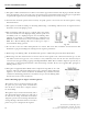
4.8 Pressure Regulator
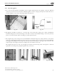
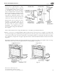
4.8.1 Introduction (Fig. 4-86)
A FlashShield™ CSST system using line gas pressures above the maximum appliance input rating shall use a regulator to
lower the downstream appliance supply pressure to 1/2 PSI, or less. e regulator shall have a lock-up feature that will limit
the downstream pressure to 1/2 PSI. Line gas pressures at or below the maximum appliance input rating does do not require
the use of a line regulator.
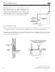
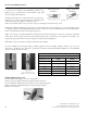
A Line Gas Regulator is defined as a pressure regulator placed in a gas line between the service regulator and the appliance
regulator. Regulators supplied by Gastite Division are designed to supply the highest performance as Line Gas Regulators
and feature precise regulating control from full flow down to pilot flows.
Regulators must be rigidly installed. is can be achieved by rigidly mounting or piping into a rigid gas-piping component.
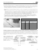
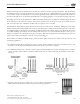
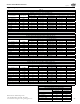
4.8.2 Sizing Instructions
Line Pressure Regulator Selection (Tables 4-7 through 4-10).
Line pressure regulators are typically used in a 2 or 5 PSI gas piping installation to reduce supply pressure to the appliance
within required operating ranges (typically 4"WC - 8"WC natural gas or 10"WC - 11"WC LP gas).
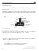
Regulators Supplied by Gastite Division:
1) For natural gas, the regulator outlet pressure is set to 8"WC and the appliance runs are sized with a 3"WC pressure drop.
is will allow for 5"WC inlet pressure at the appliance.
2) For propane gas, the regulator outlet pressure is set to 11"WC and the appliance runs are sized with a 0.5"WC drop. is
will allow for a 10.5"WC inlet pressure at the appliance.
To select the correct regulator for pressure regulation, the following information must be established:
• Available inlet pressure range at the regulator inlet.
• Desired outlet pressure.
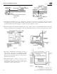
• Total maximum flow rate vs. regulator model number (Table 4-7 through Table 4-9).
• Largest single appliance flow rate vs. regulator model number (Table 4-10).
Section 4: Installation Practices
Fig. 4-86