
Brochure

Gastite Division, Titeflex Corporation
1116 Vaughn Parkway / Portland, TN 37148
800.662.0208 / www.gastite.com / gastite@gastite.com
62
April 2015
Section 4: Installation Practices
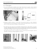
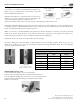
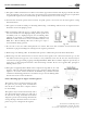
e Angle Stub is designed to create a secure mounting point
or stub-out for the transition from FlashShield™ CSST to log-
lighters, gas logs, or firebox insert’s controls. Refer to Fig. 4-82
below for Angle Stub Installation.
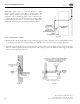
e Angle Stub shall not be connected in such a way that the log-
lighter, gas log, or other components angle out of the fireplace. To
correct for the insertion angle into the firebox, metal
shims such as fender washers can be used. (See the proper and improper installation Fig. 4-79)
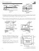
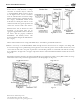
FlashShield™ Mechanical Fittings are approved to be concealed and can be connected directly to a valve controlling gas flow
to a fireplace appliance. e FlashShield™ CSST and valve connection can be installed behind the wall, beneath the floor,
hearth, or behind the brickwork of the fireplace (Fig. 4-81).
Where it is necessary to install FlashShield™ through masonry materials in fireplace construction, the plastic jacket shall
remain intact and the tubing should be routed through sleeving that is appropriate for the application. Sleeving is not
required through ceramic liners in decorative fireplaces and heat generating fireplaces.
FlashShield™ may not be run above the flue within a masonry chimney.
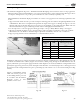
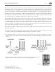
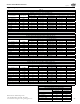
In certain configurations corrugated tubing or flexible appliance connectors feeding a fireplace, firepit or gas log set can
whistle due to gas flow velocity. Acoustics can usually be avoided by restricting FlashShield™ CSST sizes to the maximum
capacity as shown in Table 4-6 below.
Table 4-6
Fireplace/Fire Pit
FlashShield™ Size EHD BTUH
1/2" 18 45,000
3/4" 23 80,000
1" 31 125,000
1-1/4" 37 195,000
1-1/2" 48 285,000
2" 60 475,000
Fig. 4-79
Improper Angle Stub
Installation
Proper Angle Stub
Installation
Fig. 4-80
Fig. 4-81
Note: Strike Protection
(Floppy) not shown for clarity.
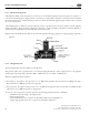
Fig. 4-82
ANGLE STUB-OUT (Fig. 4-82)
1) Attach XR3 female fitting to short end of Stub-Out.
2) Insert long end of Angle Stub-Out through metal insert knockout.
3) Secure Stub-Out utilizing sheet metal screws at the four mounting points.
4) Insert CSST into the female fitting and complete fitting assembly.
5) Refer to Section 4.6.4.