
Brochure

Gastite Division, Titeflex Corporation
1116 Vaughn Parkway / Portland, TN 37148
800.662.0208 / www.gastite.com / gastite@gastite.com
54
April 2015
Section 4: Installation Practices
4.3.9 Clearance From the Underside of a Roof Deck
a) A minimum of 3 inches of separation should be maintained from the underside of a shingled roof deck to take into
account the potential of roof nail penetration due to future repair and/or replacement of the roof.
4.4 Strike Protection
Concealed FlashShield™ CSST should be routed in areas that will minimize the opportunity for physical damage and/or
installed in areas where the tubing will be free to move to avoid a potential puncture threat. e tube can be considered free
to move when there is at least the tube’s outside diameter of clearance on all sides of the tubing.
FlashShield™ CSST installed in locations subject to physical damage shall be adequately protected. e tubing shall be
protected at points of support and when passing through structural members such as studs, joists and plates. Where all three
of the following conditions exist mechanical strike protection must be used.
1) Concealed – View is obstructed by walls, and structural members.
2) Constrained – Tubing is not free to move to avoid puncture threats.
3) Within 3 inches of a potential threat – Tubing is routed in locations which are within 3 inches of drills, screws, or nails.
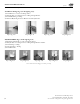
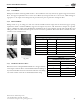
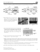
4.4.1 Strike Plates
For FlashShield™ CSST which meets all three of the conditions above, the required method for protecting concealed tubing
is hardened steel striker plates listed for use with corrugated stainless steel tubing systems. Striker plates are used at all points
of penetration through studs, joists, plates or similar structures (Figures 4-46, 4-48, 4-49, and 4-50). Striker plates other than
those provided or specified by Gastite are strictly prohibited.
e extent of protection shall be defined as follows:
a) At concealed support points and points of penetration less than 2 inches from any edge of a stud, joist, plate, etc., a listed striker
plate is required at the area of support to provide coverage for 5 inches from the point of restraint in one or both directions.
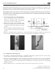
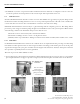
Fig. 4-48 Fig. 4-49
Fig. 4-47
Fig. 4-50
Note: Steel Stud
Construction –
Knock teeth off striker
plate for steel stud
construction.
Fig. 4-46
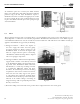
Non-Metallic Hose
Protection