
Brochure

Gastite Division, Titeflex Corporation
1116 Vaughn Parkway / Portland, TN 37148
800.662.0208 / www.gastite.com / gastite@gastite.com
51
April 2015
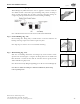
4.3 Routing
4.3.1 Vertical Runs
Tubing runs should be relatively plumb and free to move within the wall cavity without any physical support between the
floors. For support requirements refer to Section 4.1.f. Where any run is greater than two stories or 20-ft, additional support
(appropriate to the weight of the tubing) must be provided at the point of penetration through the floor.
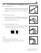
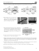
4.3.2 Horizontal Runs
Tubing routed on top of ceiling joists and other structural members which comply with the horizontal support spacing
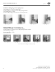
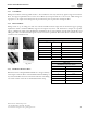
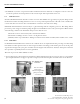
requirements will be considered sufficiently supported. See Figures 4-39, 4-40, 4-41 and 4-42 for examples of acceptable
support configurations when routing FlashShield™. FlashShield™ may be routed beneath, through and alongside floor and
ceiling joists. Due consideration must be given to future construction possibilities. Horizontal runs in concealed areas must
conform to Section 4.4 Protection.
Table 4-3
Support Spacing (Non-Rooftop, Non-Wall Cavity)
FlashShield™ Size EHD Vertical or Horizontal
1/2" 18 6 Feet
3/4" 23 8 Feet (USA) 6 Feet (Canada)
1" 31 8 Feet (USA) 6 Feet (Canada)
1-1/4" 37 8 Feet (USA) 6 Feet (Canada)
1-1/2" 48 8 Feet (USA) 6 Feet (Canada)
2" 60 8 Feet (USA) 6 Feet (Canada)
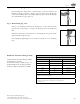
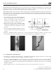
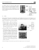
4.3.3 Installation Clearance Holes
Clearance holes for routing FlashShield™ CSST are to be approximately
1/2 inch greater than the O.D. of the FlashShield™ CSST. Drilling of
any structural member must be in conformance with the local building
code. Refer to Table 4-4 for the recommended drill hole sizing.
Table 4-4
FlashShield™ Clearance Holes
FlashShield™ Size Drill Hole Size (min)
1/2" 1-1/4"
3/4" 1-1/2"
1" 1-3/4"
1-1/4" 2"
1-1/2" 2-1/4"
2" 3"
Section 4: Installation Practices
Fig. 4-39
Fig. 4-41
Fig. 4-40
Fig. 4-42