
Brochure

Gastite Division, Titeflex Corporation
1116 Vaughn Parkway / Portland, TN 37148
800.662.0208 / www.gastite.com / gastite@gastite.com
45
April 2015
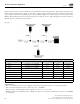
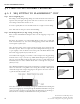
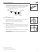
Step 3 Install Nut and Bushings (Fig. 4-12)
read fitting body (NPT thread) into valve or appliance connection. Slide nut
onto CSST and back a few inches. Separate bushings and position on tubing as
shown, locating large bump into the valley of the first corrugation leaving one
corrugation-peak exposed between the end of the bushing and tubing.
Note: Metallic shield contact feature must be utilized with FlashShield.
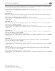
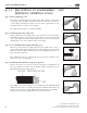
Step 4 Position Bushings (Fig. 4-13)
Insert bushings into fitting body. A small amount of resistance indicates the
bushings are being compressed to further capture the jacket.
Note: Pipe dope or sealant is not to be used inside the fitting.
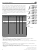
Step 5 Wrench Fitting (Fig. 4-14)
Slide nut over bushings and thread onto fitting body. Some resistance will be
experienced as the nut begins to compress the tubing and create the double-wall
flare. Continue to wrench the nut until the resistance increases greatly and the
double-wall flare is tightly seated.
Note: Rotate the nut only during the tightening process. Do not rotate the fitting body.
Note: e use of XR3 series ttings in combination with Gastite yellow tubing
is an acceptable practice.
Section 4: Installation Practices
Fig. 4-12
Fig. 4-13
Fig. 4-14