
Brochure

Gastite Division, Titeflex Corporation
1116 Vaughn Parkway / Portland, TN 37148
800.662.0208 / www.gastite.com / gastite@gastite.com
44
April 2015
. F F A P
..
™
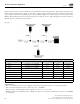
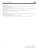
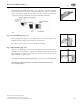
Step 1 Cut-to-Length (Fig. 4-8)
Cut tubing to desired length using tubing cutter. Cut should be centered in a cor-
rugation valley. Use light roller pressure with extra rotations in one direction to
leave tubing round and free of burrs on cut.
To ensure a quality flare, all cuts should be made on a straight section of tubing.
Note: Tube ends are sharp use caution when handling.
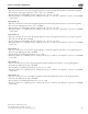
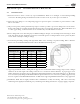
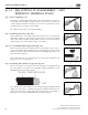
Step 2 Cut & Strip Jacket Layers (Fig. 4-9, Fig. 4-10, Fig. 4-11)
Place cut-end of FlashShield™ tubing into Side 1 of the stripping tool up to the
tube stop.
Cut: Close the stripping tool around tubing. Begin rotating the tool back and
forth on the CSST (3 – 5, 200º twists) while applying pressure until the blades
cut through all 3 jacket layers.
Strip: To remove jacket section, release pressure and grasp the tool from the end
(left end in picture). Pull tool straight away from tubing while allowing the tool
to open slightly so that the blades can clear the peak of the CSST. Remove and
discard the stripped jacket layer(s) from the tool.
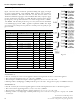
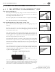
Second Cut: Turn stripping tool around to side 2 and place the stripped tubing
end back in the tool up to the tube stop. While maintaining the tube against the
tube stop, apply medium closing pressure and rotate the tool back and forth on
the CSST (3-5, 200 twists) until the blades have cut through the outer plastic
jacket layer only.
Strip: Maintain medium closing pressure and pull the tool straight away from the
tube to use the blades to strip off the outer coating. Occasionally, a small portion
of material may prevent complete stripping. Use the pliers at the corner of the tool
to grab the material and pull it away.
Note: Care is needed to avoid cutting through the aluminum shield during this
jacket layers stripping step. Cutting through the aluminum shield below the point
of the outer jacket cut/strip location will reduce the effectiveness of the fitting-to-
shield electrical continuity, and FlashShield’s electrical performance.
Section 4: Installation Practices
Fig. 4-8
Fig. 4-9
Fig. 4-10
Fig. 4-11