
Brochure


Gastite Division, Titeflex Corporation
1116 Vaughn Parkway / Portland, TN 37148
800.662.0208 / www.gastite.com / gastite@gastite.com
i
April 2015
Table of Contents
Section 1.0 introduction
1.1 General User Warnings .................................................................................................... 1
1.2 Limitations of the Guidelines ..........................................................................................3
1.3 Standards, Listings and Codes .........................................................................................3
Section 2.0 SyStem deScriptionS & componentS
2.1 System Descriptions ........................................................................................................4
2.1.2 FlashShield™ System Description ................................................................................4
2.2 Components ...................................................................................................................5
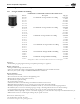
2.2.1 Corrugated Stainless Steel Tubing ............................................................................... 5
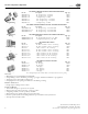
2.2.2 Fittings ................................................................................................................. 6-7
2.2.3 Manifolds ................................................................................................................. 8
2.2.4 Modular Stub System ................................................................................................8
2.2.5 Mounting Hardware .................................................................................................9
2.2.6 Pipe Support System ..................................................................................................9
2.2.7 Strike Protection .....................................................................................................10
2.2.8 Shut-Off Valves and Quick Connects .......................................................................10
2.2.9 Gastite Accessories ...................................................................................................11
2.2.10 Bonding Clamps ...................................................................................................11
2.2.11 System Identification .............................................................................................11
2.2.12 Regulators ............................................................................................................. 12
Section 3.0 SyStem configuration
3.1 Configuration ...............................................................................................................14
3.1.1 Introduction ...........................................................................................................14
3.1.2 System Requirements ..............................................................................................14
3.1.3 Reference Data for Proper System Sizing ...................................................................14
3.1.4 Determining System Layout ............................................................................... 15-16
3.1.5 Allowable Pressure Drop ..........................................................................................17
3.1.6 Sizing Methods ................................................................................................. 17-18
3.1.7 Modifying an Existing System ..................................................................................18
3.2 Sizing Procedures and Exercises ....................................................................................18
3.2.1 Sizing Examples ...................................................................................................... 18
3.2.2 Example 1 - Series System – 6"WC .................................................................... 19-20
3.2.3 Example 2 - Parallel System – 6"WC ................................................................. 21-22
3.2.4 Example 3 - Parallel System – 12-14"WC .......................................................... 23-24
3.2.5 Example 4 - Dual Pressure System – 2 PSI Trunk and 8"WC Appliance Runs ..... 25-26
3.2.6 Example 5 - Multiple Manifold System .............................................................. 27-28
3.2.7 Example 6 - Series System – 7"WC - Hybrid ...................................................... 29-30
3.2.8 Example 7 - Parallel System – 7"WC – Hybrid ................................................... 31-32
3.2.9 Example 8 - Summation Method for Parallel System – 7"WC – Hybrid ............... 33-34
3.2.10 Example 9 - Summation Method for Series System – 6"WC............................... 35-37
3.2.11 Example 10 - Commercial Elevated Pressure Series System – 2 PSI ..................... 38-39
3.2.12 Example 11 - Commercial Hybrid System – 7"WC ............................................ 40-42
Section 4.0 inStallation practiceS
4.1 General Provisions ......................................................................................................... 43
4.2 Field Fitting Assembly Procedure ..................................................................................44
4.2.1 XR3 Fitting to FlashShield CSST....................................................................... 44-45
4.2.2 XR3 Fitting to FlashShield CSST (without stripping tool) ................................... 46-47
4.2.3 FS Fitting to FlashShield CSST ...............................................................................49
4.2.4 Other Accessory Installation .....................................................................................50
4.3 Routing .........................................................................................................................51
4.3.1 Vertical Runs ..........................................................................................................51
4.3.2 Horizontal Runs .....................................................................................................51
4.3.3 Installation Clearance Holes ....................................................................................51
4.3.4 Concealed Fittings ................................................................................................... 51
4.3.5 Modifications to Existing Systems .............................................................................52