
User Manual
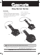
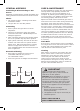
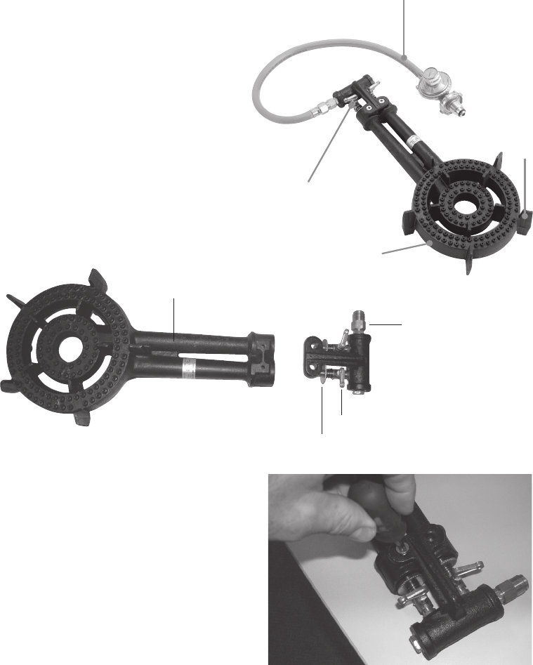
RING BURNER COMPONENTS (Image as guide only)
1. Hose and Regulator assembly
2. Gas valve
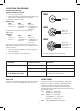
• RB2 - screws on top
• RB3 - screws from underside
• RB4 - screws from underside
3. Burner
• RB2 - 2 rings
• RB3 - 3 rings
• RB4 - 4 rings
4. Trivets - to stand cooking pot on
Note: Remove any transit
protection material before using
the burner.
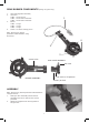
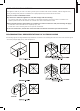
ASSEMBLY
Note: Remove any transit protection material before
using the burner.
1. Slide gas valve assembly into the burner
assembly and secure with the two screws
provided.
2. Attach the supplied hose and regulator to
the gas inlet.
4
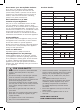
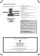
BURNER ASSEMBLY
GAS VALVE ASSEMBLY
Venturi tube
Gas valve in off position
Gas inlet
Primary air disk
3
2
1
4