INSTALLATION AND OPERATION INSTRUCTIONS OWNER / INSTALLER: For your safety this manual must be carefully and thoroughly read and understood before installing, operating or servicing this heater. INFRARED RADIANT TUBE HEATER Single Stage Push Through System (Positive Pressure) Models: PTS SERIES: (40, 50, 75, 100, 125, 150, 175, 200) – N5/L5 PTU SERIES: (40, 50, 75, 100, 125, 150, 175, 200) – N5/L5 ^ INSTALLER: This manual is the property of the owner.
TABLE OF CONTENTS SECTION 1.0) 2.0) 3.0) 4.0) 5.0) 6.0) 6.1) 7.0) 7.1) 8.0) 8.1) 8.2) 9.0) 10.0) 10.1) 10.2) 10.3) 11.0) 11.1) 11.2) 11.3) 12.0) 12.1) 13.0) 14.0) 15.0) 16.0) 17.0) 17.1) 18.0) 19.0) 20.0) 21.0) 22.0) 23.0) 23.1) 23.2) 23.3) 23.4) 24.0) 25.0) DESCRIPTION PAGE Safety........................................................................................................................................ Installer Responsibility.................................................................
1.0) SAFETY This heater is a self-contained infrared radiant tube heater. Safety information required during installation and operation of this heater is provided in this manual and the labels on the product. The installation, service and maintenance of this heater must be performed by a contractor qualified in the installation and service of gas fired heating equipment. All personnel in contact with the heater must read and understand all safety information, instructions and labels before operation.
heater. Each installer shall use quality installation practices when locating the heater and must give consideration to clearances to combustible materials, vehicles parked below, lights, overhead doors, storage areas with stacked materials, sprinkler heads, gas and electrical lines and any other possible obstructions or hazards. Consideration also must be given to service accessibility.
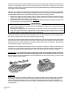
4.0) MINIMUM CLEARANCES TO COMBUSTIBLES Combustible material must be located outside the clearance dimensions listed. Failure to do so may result in death, serious injury or property damage. Minimum clearances to combustibles shall be measured from the outer surfaces as shown in the following diagram: End End Ceiling * Ceiling Front Side Below Side Rear Below 45° Angle (Maximum) Horizontal MINIMUM CLEARANCES TO COMBUSTIBLES Model No.
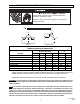
5.0) SPECIFICATIONS Model No. Btu/hr Input Combustion Air Plate Part # PTS/PTU 40 PTS/PTU 50 PTS/PTU 75 PTS/PTU 100 PTS/PTU 125 PTS/PTU 150 PTS/PTU 175 PTS/PTU 200 40,000 50,000 75,000 100,000 125,000 150,000 175,000 200,000 #44140061 #44140064 #44140063 #44140062 #44140066 #44140067 #44140067 #44140068 Orifice Size Natural Gas #32 (0.116) 3.5mm (0.138) #21 (0.159) #12 (0.189)) #4 (0.209) “A” (0.234) “E” (0.250) 6.9mm (0.272) Propane Gas #49 (0.073) 46 (0.081) 2.5mm (0.098) #32 (0.116) #30 (0.
BURNER PACKAGE NUMBERS: NATURAL GAS MODEL NO PTS/U 40-N5 PTS/U 50-N5 PTS/U 75-N5 PTS/U 100-N5 PTS/U 125-N5 PTS/U 150-N5 PTS/U 175-N5 PTS/U 200-N5 PROPANE GAS MODEL NO PTS/U 40-L5 PTS/U 50-L5 PTS/U 75-L5 PTS/U 100-L5 PTS/U 125-L5 PTS/U 150-L5 PTS/U 175-L5 PTS/U 200-L5 PART NO. #44149010 #44149030 #44149050 #44149070 #44149090 #44149110 #44149130 #44149150 PART NO.
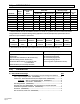
C) PTS 40-200 Series Body Package Descriptions – ALC Option (Aluminized Calorized) (Package Part Number is indicated on the outside of carton.) System Lengths 10 Ft. Pkg 20 Ft. Pkg 30 Ft. Pkg 40 Ft. Pkg 50 Ft. Pkg 44134020 44135020 44136020 44137090 44138080 PTS Body Packages – Aluminized/Aluminized or Alumi-Therm/Aluminized Part # 42912080 42912169 41932100 43319100 30462980 43318000 43980010 Each Body Package Includes: 10 Ft. Tube with 24 Hole Flange (Aluminized) 10 Ft.
Body Fastener Kit (included in body packages) 42873000 U-Bolt 02127110 Hex Nut, 5/16-18 02189020 HWHSM Screw, #10-16 x ½” TEKS 42907190 2 5 8 42907210 4 8 14 42907210 4 8 14 42907221 6 13 24 U-Bend Package U-Bend 31” Tube Support/Hanger Bracket Tube Coupling HWHSM Screw, #10-16 x ½” TEKS 43208020 1 1 1 2 43208020 1 1 1 2 43208020 1 1 1 2 43208020 1 1 1 2 42873000 43318500 30462980 02189020 60Ft.
Body Fastener Kit (included in body packages) 42873000 U-Bolt 02127110 Hex Nut, 5/16-18 02189020 HWHSM Screw, #10-16 x ½” TEKS 42873000 43318500 30462980 02189020 U-Bend Package U-Bend 31” Tube Support/Hanger Bracket Tube Coupling HWHSM Screw, #10-16 x ½” TEKS 42907190 2 5 8 42907210 4 8 14 42907210 4 8 14 42907221 6 13 24 43208020 1 1 1 2 43208020 1 1 1 2 43208020 1 1 1 2 43208020 1 1 1 2 60Ft.
C) Corner Reflector Accessory Package, Part #43342000 (Option for PTS Series Only) 24 (61cm) Contains: Corner Reflector Assembly, #43345000……QTY–1 Speed Clips, #02266010……QTY–4 24 (61cm) 18 (46cm) D) U-Bend Package, Part #43208020 (Option for PTU Series Only) Contains: U-Bend, #42913020……QTY–1 #10-16 x ½ Self-Drilling Screws, #02189020……QTY–2 Tube Coupling, #30462980……QTY–1 31” Hanger/Tube Support, #43318500……QTY–1 E) U-Bend Reflector Package, Part #43488000 (Option for PTU Series Only) Contains: U-
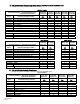
7.0) TYPICAL LAYOUTS – PTU / PTS Series 10FT. SYSTEM 50 FT. SYSTEM 20 FT. SYSTEM 30 FT. SYSTEM 60 FT. SYSTEM 40 FT. SYSTEM LEGEND Burner Box 5 FT. Body Section Flue Termination 90 Deg. Elbow 10 FT. Body Section 180 Deg. U-Bend MODEL PTS 40 EMITTER LENGTH Min. Max. 10 Ft. 20 Ft. 70 FT. SYSTEM MODEL PTU 40 BODY LENGTH Min. Max. 10 Ft. 10 Ft. PTS 50 20 Ft 30 Ft. PTU 50 10 Ft. 15 Ft. PTS 75 20 Ft. 30 Ft. PTU 75 10 Ft. 15 Ft PTS 100 30 Ft. 40 Ft. PTU 100 15 Ft. 20 Ft.
above. 7.1) TYPICAL ASSEMBLY LAYOUT POISONOUS GAS AND SOOT HAZARD The heater must be assembled with the correct number of turbulator sections and tube length for the rated heat input. The turbulator must be installed in the last tube section as shown. Failure to do so may result in death, serious injury, property damage or illness from Carbon Monoxide poisoning. 10 FT. SYSTEM Stainless Steel Turbulator closest to burner PTS / U 40 only.
Form #43343330 May 08 Burner Box –13– Models: PTS 150, 175, 200 Models: PTS 125, 150, 175, 200 Models: PTS 100, 125 150 Models: PTS 50, 75, 100, 125 Models: PTS 40, 50, 75 14 (36cm) Models: PTS 40 14 (36cm) Bottom View 108 (274cm) 12 (30cm) 12 (30cm) 12 (30cm) 12 (30cm) 108 (274cm) 12 (30cm) 12 (30cm) 12 (30cm) 108 (274cm) 4 Tube Coupling (typical) 108 (274cm) 4 Tube Coupling (typical) 108 (274cm) 108 (274cm) 13 Tube Support/ Hanger Bracket 12 (30cm) Wire Hang
8.1) DIMENSIONS – PTU Series Typical Dimensions Up to 50 Ft. Shown.
Form #43343330 May 08 –15– Burner Box Gasket Burner Box Suspension Chain Maximum 6 distance from burner box to the tube support/hanger bracket. 8 - 9 ¼ 8 - 10 U-Bolt Clamp & 5/16" Hex Nuts Mounting Flange 24 Hole for Aluminized Steel Tubes 6 Hole for Alumi-Therm Steel Tubes 4"OD x 10Ft. Tube See section 7 for required tubes. Typical Assembly Overview (PTS 40FT Shown) Wire Hanger Not Less Than 10 #10 Self-Drill Screws (Typical all tube supports, tube couplings and flue terminal.
Typical Assembly Overview (PTU 40FT Shown) Reflector Typical Overlap U-Bend Turbulator (See specifications section 5 for required quantities.) Tube Coupling (Typical each tube joint.) #10 Self-Drill Screws (2 each) 13 Tube Support Brk. with U-Bolt Clamp & 5/16" Hex Nuts Wire Hanger Flue Terminal Gasket Burner Box 31 Tube Support Brk. with U-Bolt Clamp & 5/16" Hex Nuts #10 Self-Drill Screws (Typical all tube supports, tube couplings and flue terminal.) 4"OD x 10Ft.
9.0) TYPICAL SUSPENSION METHODS SUSPENSION HAZARD Burner must be secured to the mounting flange with nuts. All materials used to suspend the heater must have a minimum working load of 115 lbs. All S Hooks must be crimped closed. Never use the heater to support a ladder or other access equipment. Failure to do so may result in death, serious injury or property damage. Various means of suspending the heater can be used. See the following drawings for typical examples. 1.
10.0) ASSEMBLY OF TUBE SECTIONS CUT HAZARD Sheet metal parts, particularly reflectors and vent have sharp edges. Always use gloves when handling. Failure to do so may result in death, serious injury or property damage. During field assembly of the heater body sections, the recommended procedure is as follows: 1. Before hanging heater sections, first determine the actual layout of the system (see Sections 7.0 & 8.0 for details).
10.1 ASSEMBLY OF EXTENSION SECTION MIN 8 MAX 10 BETWEEN HANGERS 1 Coupling 2 Wire Hanger 3 U-Bolt Clamp & 5/16 Hex Nuts Tube Support/ Hanger Bracket Tube Support/ Hanger Bracket 6 approx. See typical assembly overview (Section 8.0) for typical complete assembly. Assemble additional extension sections as required for all systems. (See Sections 7.0, and 8.0 for typical layout details.
4 Tube Coupling 4. 5. 6. 7. 5 Center both tubes with hole 7 #10 Self-Drilling Screws (QTY 2) 6 Slide the next tube into the coupling. Make sure both tube ends are butted together. Finish tightening both bolts to 40-60 ft.lbs. torque to ensure a complete seal. Use the two Self-drilling screws through the pre-punched holes to secure the tubes in the coupling. Band Force Bars Reaction Block Bolt Interference Pins CORRECT INSTALLATION INCORRECT INSTALLATION 8.
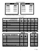
Turbulators MODEL PTS/U 40 PTS/U 50 PTS/U 75 PTS/U 100 PTS/U 125 PTS/U 150 PTS/U 175 PTS/U 200 10.3) 2 Ft. Turbulator Sections 4 5 5 3 7 4 0 1 ASSEMBLY HAZARD The PTS / U 40 has one stainless steel turbulator. This must be installed closest to the burner. Failure to do so may result in deterioration of the turbulator material and invalidate the warranty. ADDING REFLECTORS 1. Slide the reflectors on the tube support/hanger brackets and through the wire hangers. 2.
11.0) ADDING OPTIONAL 90º ELBOW (PTS ONLY) 1. The optional 90º elbow must be located a minimum of 10 ft. after the control box. 2. Hang the body sections in a 90º ("L") shaped pattern. Allow spacing for the elbow. The distance from one end of the elbow to the centerline of the opposite leg is 13" as shown. 3. Join the tube ends of the body sections and the elbow together and secure with tube couplings as described in Section 10.1. Tube Coupling 90 Deg.
11.2) ADDING 180°U-Bend (PTU ONLY) 1. Hang body sections parallel with each other. The centerline distance from tube at each body section should be 18” as shown. 2. Join tube ends of body sections and the U-Bend together and secure with tube couplings as described in Section 10.1. Self-Drilling Screws (QTY-2 per coupling) Tube Coupling 18 (457mm) U-Bend 11.3) ADDING OPTIONAL U-BEND REFLECTOR (PTU ONLY) 1.
12.0) ATTACHING BURNER BOX ASSEMBLY 1. Attach the burner box and gasket to end of tube flange and secure with 1/4-20 locknuts. 2. Assemble the optional end reflector flush with the end of the main body reflector. Secure by sliding speed clips onto the reflector edges. Evenly space the speed clips on the sides (one each side) and top (two required) of the reflectors to provide a snug fit. Leave a 3" space between the end reflector and the burner box assembly. 3.
12.1) CONNECTING THE TISS SYSTEM Description: The TISS (Tube Integrity Safety System) is designed to shut the main burner off in the event that a burnout occurs in the first 10ft. section of firing tube. Note: When replacing the firing tube a new TISS wire assembly PN 44176010 must also be installed. Instructions: 1. Make sure that the gap between the burner box and end of reflector is 3” and the reflector is securely attached to the reflector support bracket. Make adjustments if necessary.
3. Hold the spring retainer clamp and pull the TISS wire assembly to end of reflector at overlap joint. Slide spring retainer clamp over end of reflector as shown. Step 3 Thimble End View Spring Retainer Clamp Spring Wire & Sleeving Assembly TISS Wire Assembly PN 44176000 4. After attachment of the TISS, check to make sure that there is sufficient tension on the wire. Follow the diagram below to increase or decrease the tension as necessary. 1.
ANGLE MOUNTED HEATERS ONLY 5. If heaters are to be angle mounted, the TISS wire holder clamp must first be re-positioned as shown using the bottom hole pattern of the clamp. Follow procedures described earlier for all other adjustments. Re-position wire clamp using bottom hole pattern.
13.0) GAS CONNECTIONS AND REGULATIONS Tighten flexible gas hose and components securely. Flexible metal gas hoses must be installed without any twists or kinks in them. The hose will move during operation of the heater and it can crack if it is twisted. Failure to do so may result in death, serious injury or property damage. IMPORTANT BEFORE CONNECTING THE GAS TO THE HEATER 1. Connect to the supply tank or manifold in accordance with the latest edition of National Fuel Gas Code (ANSI Z223.
KEY DIMENSIONS AND COMPONENTS OF THE GAS CONNECTIONS Gas Pressure = 2 PSIG Gas Supply Piping Approved Flexible Connector *Manual Gas Shut Off Valve Sediment Trap (Drip Leg) 14 to 17 (36 to 43cm) 2 (5cm) Max. Displacement *Second Stage Regulator with Vent Leak Limiter to reduce the Supply Pressure below 14 W.C. * Available as Accessories Burner Movement RECOMMENDED GAS CONNECTION POSITIONS WITH 36 FLEXIBLE GAS HOSE DO NOT install gas connector vertically if fresh air is to be connected.
14.0) INSTRUCTIONS FOR PRESSURE TEST GAUGE CONNECTION Never operate the heater with the access panel open or removed. The access panels must be closed tightly with all the necessary screws during operation. Failure to do so may result in death, serious injury or property damage. The access doors on either side of the burner must be securely fastened before operating the heater. DANGER FIRE HAZARD Never operate the heater with the access panel open or removed.
CAUTION Never jumper these terminals. This shorts out valve coil and may burn out heat anticipator in thermostat. Pressure Regulator Adjustment (under cap screw) Wiring Terminals (2) 1/8 NPT Inlet Pressure Tap with 3/16 Hex Allen Wrench Plug MV MV Ground Terminals (2) OUTLET INLET ON OFF STEP-OPENING GAS CONTROL VALVE 15.
INTERNAL CONNECTION WIRING DIAGRAM — Direct Spark Ignition Optional Low Voltage (24V) Thermostat Remove jumper wire. Terminal Block Red Red Air Switch pressostat Ignition Module (Fenwal) Bloc d'allumage P.
FIELD CONNECTION WIRING DIAGRAMS A. LINE VOLTAGE (120V) THERMOSTAT CONNECTIONS – SINGLE HEATER N L1 Ground Neutral Hot (120V) Continue To Additional Heaters Fused Disconnect switch Receptacle Power Supply Cord (120V) Line voltage thermostat C TH Jumper factory installed for optional 24V thermostat C TH Burner Control Box B.
D. LOW VOLTAGE (24V) THERMOSTAT CONNECTIONS – MULTIPLE HEATERS (utilizing a fan center relay) Receptacle Ground N Neutral L1 Hot (120V) Continue To Additional Heaters Burner Control Box Fused Disconnect switch C 24V R Fan Center Relay Part No. 30169000 Contact Rating: 120V, 40VA, 12A (maximum of 6 heaters per relay) 16.
SINGLE HEATER VENTING (VERTICAL THROUGH THE ROOF) 1. When venting the heater to outside of building through a roof, use single-wall metal pipe. This is to be constructed of galvanized sheet metal or other approved noncombustible corrosion-resistant material as allowed by state or local codes. 2. A vent passing through a combustible roof shall extend through an approved clearance roof thimble. Double-wall, Type B vent must be used for the portion of the vent system which passes through the roof.
7. The horizontal venting system shall not terminate: a. Less than 4 ft. (1.2m) below, 4 ft. (1.2m) horizontally from or 1 ft. (30cm) above any door, operable window or gravity air inlet into any building. The bottom of the vent terminal shall be located at least 7 ft. (2.1m) above grade or above snow accumulation level as determined by local codes. b. Less than 3 ft. (0.9m) from a combustion air inlet. c. Less than 3 ft. (0.9m) from any other building opening or any gas service regulator. d.
Multiple Heater Vertical venting arrangement. Vent Cap (Leslie VersaCap Type B) 2 ft (77cm) minimum (when no wall or parapet exists) 2 (5cm) Clearance Thimble See multiple vent size table for diameter Seal Joint and Annular Space Wall or Parapet Flashing Total Vent Height 2 ft (77cm) minimum 10 ft (305cm) or less 4 Diameter single wall Vent Flue Collar adaptor Connections to the common vent must be arranged to avoid direct opposition of exhaust products.
B. INDIRECT VENTING (UNVENTED HEATERS) — This heater requires ventilation in the building to dilute the products of combustion and provide fresh air for efficient combustion. Where unvented heaters are used, gravity or mechanical means shall be provided to supply and exhaust at least 4 CFM per 1,000 Btu/hr input of installed heaters. Exhaust vents must be located at the highest point above and in the vicinity of the heaters, and the inlet vents must be located below the level of the heaters.
In multiple heater applications, the combustion air intake may be ducted individually or common ducted in the same configuration as shown for venting in Section 16.0. For combustion air intake duct sizing, please refer to the Vent Sizing Table and use the diameter indicated, based on the number of heaters per duct. Vertical Through the roof Combustion Air Cap (Leslie VersaCap Type B) 4 Diameter Single-Wall Pipe 3 ft. (91cm) Minimum Flashing 4 Spring Tension Clamp (2 each) (Part No.
18.0) LIGHTING AND SHUTDOWN INSTRUCTIONS Never operate the heater with the access panel open or removed. The access panels must be closed tightly with all the necessary screws during operation. Failure to do so may result in death, serious injury or property damage. The access doors on either side of the burner must be securely fastened before operating the heater. DANGER FIRE HAZARD Never operate the heater with the access panel open or removed.
Note1: When the PTS / PTU is operated by a thermostat interrupting the line voltage (120V) to the heater then the post purge function is disabled. If the flame is not sensed during sequence T3 then the burner will automatically begin re-ignition sequence T2. The ignition sequence will be repeated three times with a 60 second inter-purge. If the flame is not re-established the heater will go to lockout. 20.
21.0) CLEANING AND MAINTENANCE ELECTRIC SHOCK & EXPLOSION HAZARD Disconnect electrical power and gas supply before servicing. Failure to do so may result in death or serious injury. This heater must be cleaned and serviced annually by a qualified contractor before the start of each heating season and at any time excessive accumulation of dust and dirt is observed. Maximum heating efficiency and clean combustion will be maintained by keeping the heater clean.
Form #43343330 May 08 –43– Yes Troubleshooting continued on the next page. Yes Does the amber light come on? Yes Is the blower on? Check line voltage at thermostat and line No voltage circuit. Repair fault. Remove jumper, air switch must be open circuit first for blower to operate. Replace ignition module. Yes Is the LED on the ignition module No steady ON? No Check NO terminal of the air switch connection. Replace red light. Replace ignition module.
–44– Form #43343330 May 08 Yes Replace ignition module. No No Yes No No No Repair or replace jumper check all wire terminals. No Change number of turbulators. Replace air plate. No Repair or replace flame sense electrode. No Replace flame sense wire. No Check the terminal on Remove and inspect Check flame sense the flame sense flame sense wire does it have electrode, is it tight? Yes electrode. Is it clean Yes continuity? and the ceramic intact? Adjust terminal connection.
Form #43343330 May 08 –45– Purge the gas supply lines? No Has all the air been purged from the gas supply lines? Troubleshooting continued from previous page. Replace ignition module. Yes Is the LED on the ignition module steady Yes on? Adjust supply gas pressure. Restart troubleshooting. No Check the inlet pressure to the gas vaIve. Is it No between minimum and Yes maximum for the gas type? Check electrode spark gap. Is it 1/8”? No Adjust spark gap carefully.
23.0) REPLACING PARTS ELECTRIC SHOCK & EXPLOSION HAZARD Disconnect electrical power and gas supply before servicing. Failure to do so may result in death or serious injury. Only use genuine Space-Ray replacement parts. Parts are available from the factory for replacement by a licensed person. Refer to the Replacement Parts Guide in Section 25 for all replacement parts. 23.
23.2) REMOVAL OF GAS VALVE AND MANIFOLD ASSEMBLY Step 1 Step 3 23.3) Open hinged access panel and disconnect wires from gas valve. Connector Tees Remove (6) screws from end panel. Rotate gas valve and manifold assembly slightly counter-clockwise and slide out from housing. P1 + P1 + Temporary 1/4 ID Silicone / plastic tubing for pressure test. Form #43343330 May 08 Step 4 Loosen screws from manifold clamp and burner assembly.
1. 2. 3. 4. 5. Open hinged access panel. Add tubing to connect the air switch tubing P1 + and P2 - with the connector tees and the probes P1+ and P2+. Connect plastic tubing of a digital or inclined water manometer with a 0-2” scale onto the connector tees. Turn heater on and wait until blower motor is activated. Observe air pressure from manometer. This should be higher than the set point indicated below for correct operation.
IGNITION MODULE DIAGNOSTICS Flame Fault If at any time the main valve fails to close completely and maintains a flame, the full time flame sense circuit will detect it and energize the combustion blower. Should the main valve later close completely removing the flame signal, the combustion blower will power off following the post purge period.
25.0 REPLACEMENT PARTS GUIDE – BURNER BOX Item No. Part No.
37 38 38a 39 40 40a 41 41a 42 42a 43 44 45 46 47 48 48a 48b 03946010 42752250 30504040 30701240 44145060 03333140 30333070 30333080 Sealing Strip 1/8" x 3/8" wide (access panels) -not shownAir Inlet Screen Starting Collar (combustion air inlet) Ignition Cable - Female (2) 1/4" QC x 24"lg #PSE-GF23 -not shownManifold Pipe – 6-1/4”lg Pipe Nipple – 4”lg Gas Valve #VR8205P-2408 (natural gas) Gas Valve #VR8205P-2416 (propane gas) Ft.
22 (W)TH P.
BODY COMPONENTS ITEM PART NO. 1 02266010 2 43980010 3 42873000 3a 02127110 4 43318000 5 43319050 6 43319100 7 43320000 8 43342000 9 42921000 10* 44028170 10a** 44028030 11 44028100 11a 44028060 12 44028120 12a 44028010 13 43208010 14 02189020 15 30462980 16 43208020 17 43488000 18 30504500 19 44152240 DESCRIPTION Reflector Speed Clip Wire Hanger “U” Bolt Clamp, 4” OD Tube 5/16-18 Hex Nut (2 per “U” Bolt) Tube Support/Hanger Bracket, 13” Reflector, 4’-11½” long (5’ section only; 1 per 5 ft.