
- Garrett Communications Network Router User Manual


CHAPTER 1 - Overview
Specifications
DX40 Serial Device Router Installation Guide
6
1.3.6 Ports and External Connectors
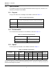
The ports and external connectors of the DX40 are defined in Table 1-6.
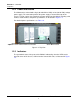
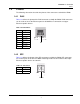
1.3.7 Indicators
The status indicators of the DX40 are described in Table 1-7. The operational status of
the ports of the DX40 is indicated by a bank of LEDs on the beveled corner of the chassis,
visible from the front and the side, as illustrated in Figure 1-3.
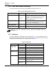
Table 1-6. Ports and External Connectors
Port Name Connector Description
Ethernet, E1 and E2
LC
or
LC + RJ45
2 100FX multi/single mode small-format pluggables
(SFP) port for fiber optic Ethernet-capable devices or
Networks, or one 100FX SFP port and one 10/100
Mbps Ethernet port for connection to copper
Ethernet-capable devices.
Serial, S1 and S2
DB9, female Connection to serial async devices. Configurable to
300, 600,1200, 2400, 4800, 9600, and 19.2, 28.8,
33.6, 38.4, 57.6, 115.2, 230.4 Kbps.
Power Connection
Terminal block Non-polarized power input.
Facility Ground Point
Screw Facility ground connection point.
8
NOTE: All copper I/O connections must be made with shielded cables and
connectors.
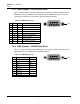
Table 1-7. Indicators
LED Name Condition Indication
S1 – S2
(Serial Ports)
Green Port is connected to an active serial device.
Off Port is down.
Flashing Data is passing through the port.
E1 – E2
(Ethernet Ports)
Green Port is connected to an active Ethernet device.
Off Port is down.
Flashing Data is passing through the port.
Power
Green Normal functioning.
Off Power not connected.
Yellow Power on but diagnostics not yet run or
diagnostics failed.
Alternating Yellow
and Green
Diagnostics in progress.