EN GARO LS4 / LS4 Compact Manual 380144 2.1 Installation Manual (EN) GARO AB Box 203, SE–335 25 Gnosjö Phone: +46 (0) 370 33 28 00 info@garo.se garo.
EN TABLE OF CONTENT Safety Information 3 General Information 3 INSTALLATION 4 NORMAL USE 5 LED light indication 5 Technical specifications 10 Service information 10 Form for annual service and maintenence 11 Warranty Conditions 12 Warranty Form / Garantiformulär 13 2
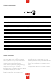
EN GENERAL INFORMATION SAFETY INFORMATION The LS4 stations are designed exclusively for charging Each LS4 station is pre-programmed from factory and electric vehicles. tested according to the specification from customer. There is no need for any programming or setup by installer All installation must be carried out by an authorized during installation. installer and comply with local country installation regulations.
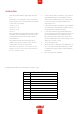
EN INSTALLATION 1. Mount the LS4 and install the supply cable. See picture 2. In cases with LS4 stations connected in a grid, install TP 1-4. cable CAT6 with RJ45 connectors between each LS4 Phase-rotation is recommended in order to achieve even station and the provided ethernet router/switch (located load on all phases when several LS4 stations are installed ie. in the LS4 master. Se example of ethernet wiring to same mains. For example: diagram picture 5, 6.
EN NORMAL USE Connect the charging cable to the EV. If authorization is activated, please hold a valid RFID-tag against the RFID reader on the side of the LS4 you want to use or use the operator app to authorize charging. Charging will start instant if the EV is ready for charging. See your EV charging manual. When finishing charging, follow the EV’s instructions. After charging: Release the charging cable from your EV and place the charging cable at designated place.
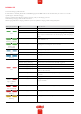
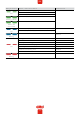
EN LED light indication When Charging station and internal meters are powerless. Cause of error The upstream circuit breaker have been triggered. 4-pole main circuit breaker inside the bottom of charging station is deactivated. 1-pole main circuit breaker inside the bottom of charging station is deactivated. The 12V power supply unit is deactivated (Green LED-light [DC NO LIGHT Charging station is powerless OK] on 12V supply unit is not lit).
EN LED light indication Measure 1 Measure 2 If the orange "alarm" LED indicator on the charge controller is firm lit, then the charge controller needs to be replaced. Reset the RCCB inside the charging station. Verify that the 8-pole quick connection on the charge controller is properly connected. Verify correct grounding and phases in building electrical system When car is connected: Disconnect charging cable from the charging station, then the LED indication shall return to GREEN.
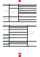
EN LED light indication Measure 1 Measure 2 Reset circuit breaker in upstream switchboard. Check mainbreaker, reset it if it is deactivated. Check mainbreaker (1-pole 10A), reset it if it is deactivated. Verify that 12V power supply unit is receiving 220V AC power via terminals L & N. Disconnect red/black cables from the power supply unit terminals marked "+/-".
EN LED light indication Indication / fault code in Web UI OCPP fault code IDLE (available) - (A) Vehicle not connected IDLE (available) - (B) Vehicle connected not ready Firm IDLE (available) - (C) Vehicle connected ready IDLE (available) - (A) Vehicle not connected Blinking (3 blinks) AUTHORIZED (available) - (A) Vehicle not connected Blinking (30 second blink) CHARGING (occupied) - (C) Vehicle connected ready Firm CHARGING (suspendedEV) - (B) Vehicle connected not ready Reserved Blinking Firm RCD
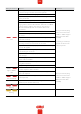
EN TECHNICAL SPECIFICATIONS Product type All LS4 models Standards / Directives IEC 61851-1 and IEC 61439-7 EMC Classification: 2014/30/EU Installation method: Ground / Wall Installation environment: Indoor / Outdoor Location type: Non-restricted Access Rated Voltage: 1-phase 230VAC 50Hz / 3-phase 400VAC 50Hz depending on model Rated Current (configurable) 63A, 32A 1-phase or 3-phase Installation systems: TT, TN and IT* systems Charging type: Mode 3 Charging method AC Charging Protecti
EN FORM FOR ANNUAL SERVICE AND MAINTENENCE Plant ID: Name: Check point for annual service and maintenence: Date: Status/Value Visual check outside cabinet LED indication lit Check cables, connectors, connector pins Check sockets Check color, foil and instructions Check external antenna (when installed) Check fastening/fixing to ground/wall Cean LS4 outside surface Check locking mechanism Check both RCCB by pressing “T” button.
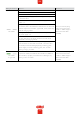
EN WARRANTY CONDITIONS EU Countries (except Sweden) 1. The product benefits from manufacturer´s warranty. The applicable warranty period must be stated in purchase documents from your supplier. 2. The product must be installed by a certified installer / contractor. 3. Proper installation, storage and operation conditions must be obtained. 4. Warranties apply only to products installed in their original installation location. 5.
EN WARRANTY FORM / GARANTIFORMULÄR LS4 Model: M no: Electrical installation data Group fuse (A): Supply cable dimension: Function Test Testbox / EV (model) Date: Sign Installer: Company Name: Owner / Customer Name: Installation adress: 13
EN CU/AL Cu = 2,5Nm Al = 4Nm (picture 1) OPTION 14 (picture 2)
EN 0,8Nm +-0,5 (picture 3) (picture 4) 15
EN 3pcs LS4 connected with TP CAT6 cable to router/switch (picture 5) 5pcs LS4 connected with TP CAT6 cable to router/switch (picture 6) Example of DLM meter installation DLM meter Modbus address #2 9600, 8, 1, no parity Terminals: #200 - A#201 - B+ 16
EN 17 Q1 = Main breaker F3 = Fuse Charge Controller and Powersupply P1 = Energymeter Left Outlet P2 = Energymeter Right Outlet FB1 = RCCB Left Outlet FB2 = RCCB Right Outlet FC1 = Fuse Left Outlet FC2 = Fuse Right Outlet QA1 = Contactor Left Outlet QA2 = Contactor Right Outlet XN1 = N Neutral terminal XPE1 = PE Terminal Protection Earth T1 = Powersupply DC CC1 = Charge Controller (Master) CC2 = Charge Controller (Slave) RFID1 = Left Receiver RFID2 = Right
EN 18
EN 19
EN 20
EN GARO AB Box 203, SE–335 25 Gnosjö Phone: +46 (0) 370 33 28 00 info@garo.se garo.