
User Manual
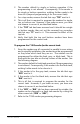
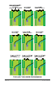
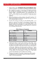
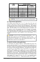
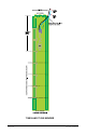
Table Of Contents

Page 18 709-RVC Manual
Wire Colours on Connector
Wire Color Function
Red 18 gauge +12V
Black 18 gauge Ground
Blue 18 gauge Tank Senders
Purple 18 gauge CAN-Hi
Yellow 18 gauge CAN-Lo
Green 18 gauge LPG tank
CHAPTER 6 - INSTALLATION GUIDE
1. Please refer to the “Troubleshooting and Installation Tips”
section in Chapter 7 for details on avoiding installation issues.
2. The installation consists of mounting the display inside the
RV, cutting and fastening the senders to the sides of the
holding tanks, connecting wiring, and programming the
display. When wiring DO NOT use spade connectors to join
wires, only use crimp on butt connectors or solder the wires
together.
3. Mount the display by cutting a hole in the wall 3” wide by 1 ⁄”
high and bringing the wiring out through the hole to connect
to the display panel connector.
4. Connect the wiring according to the following table. It is
easier to connect the wiring to the display connector rst,
and then plug the connector into the display panel. The
senders need to be grounded to a single ground wire from
the display. Make sure that the system ground is connected
to the breaker panel ground.
5. Determine where to mount the senders on the tanks. They
will need to have a at area on the side of the tank large
enough so the whole width of the sender is in contact with
the side of the tank, all the way from the top to the bottom
of the tank. Make sure that any metal is at least an 1” away
from either side or the top and bottom of the sender, and at
least 2” away from the face of the sender. Clean the area well
so that there is no dust, grease, oil, water, etc., that would
prevent the adhesive on the sender from sticking.
6. Measure the height of the tank to determine which sender
conguration to use and how long the senders should be.
Refer to the following table.