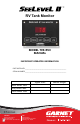
RV Tank Monitor MODEL 709-RVC MANUAL IMPORTANT OPERATOR INFORMATION DATE INSTALLED: _____________________________________________________________ SERIAL NUMBER: _____________________________________________________________ Signal Level Black Water Tank Grey Water Tank Fresh Water Tank CANADA Garnet Instruments 286 Kaska Road Sherwood Park, AB T8A 4G7 USA Garnet US Inc.
GARNET SEELEVEL II TM Tank Monitor MODEL 709-RVC Table of Contents CHAPTER 1 - OVERVIEW .............................................................................................3 CHAPTER 2 - SYSTEM DESCRIPTION .....................................................................4 CHAPTER 3 - OPERATING INSTRUCTIONS ..........................................................6 CHAPTER 4 - DISPLAY CALIBRATION .....................................................................
CHAPTER 1 - OVERVIEW he SEELEVEL II TM Tank Monitor represents a massive leap forward in level measurement technology for the Recreational Vehicle industry. The SEELEVEL™ has a combination of features, accuracy, reliability, and diagnostic capability that have never been available before. T Model 709-RVC will monitor the battery voltage, the fresh water and sewer holding tanks and the LP gas tank.
CHAPTER 2 - SYSTEM DESCRIPTION T he SeeLeveL consists of a display unit that mounts inside the RV, and sender panels that stick to the side of the holding tank. A single 2 conductor wire is used to connect all the sender panels to the display. The Sender: Each sender panel is a flexible self-adhesive printed circuit board which is adhered to the side of the holding tank.
If a sender is operating properly and connected to the display with good wiring, then the display will show the level normally. If the wiring is disconnected, shorted, or cut, or if the sender panel is defective, then the display will indicate an error code. The various error codes are shown in the troubleshooting chapter.
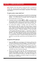
CHAPTER 3 - OPERATING INSTRUCTIONS T he display is the only system component that is accessed by the user. All user input to the display is done using the five buttons along the bottom of the display. Operation of the display is as follows: To read a water or sewer tank level: 1. 2. 3. Press the button corresponding to the tank to be checked and release it, the display will show the level in percent on the LED display. If no other button is pressed, then the display will shut off after about 5 seconds.
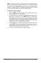
Note: If using two displays (i.e. a primary and a secondary display), then only the primary display should have a connection to the LPG tank. If both displays are connected to an LPG tank, then an incorrect reading will result. The primary display relays LPG levels to the secondary display through the sender wiring. To read the battery voltage: 1. 2. 3. 4. Press the BATT button and release it, the display will show the battery voltage on the LED display.
RV-C Bus Communication: RV-C is a communications protocol based on CAN that is used for control, coordination, and diagnostics. Note: Anyone that intends on connecting to the RV-C bus should have a knowledge of the RV-C specification. For more information on RV-C protocol go to: http://www.rv-c.com The sensors use a default source address of 72 and SPN-ISB instances are 0 for fresh, 1 for black, 2 for grey and 18 for galley (depending how the display is equipped).
CHAPTER 4 - DISPLAY CALIBRATION To calibrate the LPG sender: 1. 2. 3. 4. The LPG tank must be full when the sender is calibrated, otherwise the calibration will be invalid. Fill the LPG tank by using an alternate measurement method, such as weight, a spit valve, or a mechanical gauge on the tank. To calibrate the tank, press and hold down the LPG button, the display will show some LPG level. While continuing to hold down the LPG button, press and hold down the BATT button.
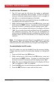
To program the LED brightness: 1. 2. 3. 4. 5. 6. If the display is to be used inside the coach, the LED brightness should be low. If it is to be used in the service bay area where sunlight can reach it, the LED brightness should be high. To program the LED brightness, the display needs to enter the brightness programming mode. To do this, press and hold down the BATT button, the display will show the battery voltage. While continuing to hold down the BATT button, press and hold down the GREY button.
5. 6. 7. The display will now show “0SE” (zero senders/disabled), “1SE” (one sender) or “2SE” (two senders), based on what is currently programmed into the display. These are the only three options; the display will not work with more than two senders per tank. To change the number of senders, press the tank button, each time the button is pressed the display will increment one number. When the display shows the correct number of senders, press the BATT button to exit the programming mode.
Trip Polarity: While the BLACK button is held down, the display shows “Hi” on the left for a high level alarm or “Lo” for a low level alarm. After the button is released, the left digit shows “H” for a high level alarm which means the alarm turns on (closes) when the fluid level is equal to or higher than the set point, and the alarm is off (open) when the fluid level is below the set point.
To check the primary/secondary mode: 1. Press and hold down the BATT button, the display will show the battery voltage. While continuing to hold down the BATT button, press and hold down the BLACK button. Continue to hold down both buttons for about 5 seconds until the display shows “Pri” for primary mode or “SEC” for secondary mode. When viewing is complete, release both buttons to return to normal operation. To check the hardware and software revision: 1. 2.
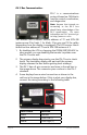
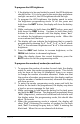
CHAPTER 5 - SENDER PROGRAMMING To program the 710ES or 710SS sender for the correct tank: 1. Since the senders are all connected in parallel to save wiring and to simplify installation, the senders must be programmed so they know which tank they are on. The senders can be programmed for either the fresh, grey, or black tank. This is done with the two tabs on the top corners of the sender. See the following diagram. 2. The senders default to fresh tank operation if the programming is not altered.
2. 3. 4. 5. 6. The senders default to single or bottom operation if the programming is not altered. Consequently, if the sender is for single or bottom operation, nothing further needs to be done to it (beyond programming it for the correct tank). For a top sender, remove the tab that says “TOP” next to it. This is all that is required to program the senders for single, top, or bottom use. However, if you make an error, you have one chance to correct it, as described below.
710ES AND 710SS SENDER PROGRAMMING Page 16 709-RVC Manual
710JS SENDER PROGRAMMING 709-RVC Manual Page 17
CHAPTER 6 - INSTALLATION GUIDE 1. 2. 3. 4. Please refer to the “Troubleshooting and Installation Tips” section in Chapter 7 for details on avoiding installation issues. The installation consists of mounting the display inside the RV, cutting and fastening the senders to the sides of the holding tanks, connecting wiring, and programming the display. When wiring DO NOT use spade connectors to join wires, only use crimp on butt connectors or solder the wires together.
Tank Height Sender Options Best Resolution 41/2” - 5” JS Other Acceptable - 5” - 7” JS ES 7” - 13” ES SS 13” - 17” stacked ES SS 17” - 25” stacked ES stacked SS 25” - 34” stacked SS - W CAUTION: DO NOT mix sender types when stacking senders. For single sender applications: The sender ends should be 1/4” to 3/4” away from the top and bottom of the tank, to allow for the thickness of the tank top and bottom and any bows in them (see the diagrams).
710ES AND 710SS SENDER Page 20 709-RVC Manual
710JS SENDER 709-RVC Manual Page 21
7. To make the senders the right length (assuming they are too long) they will need to cut off with a pair of scissors. The end to be cut is the bottom end, which is the opposite end from W CAUTION: DO NOT cut the sides, and DO NOT cut the 710ES sender shorter than 4 1/2”. The cut must be in between the sensor pads, and the cut must be made parallel to the existing bottom end. Double check your measurements, if the sender is cut too short, it cannot be lengthened.
W CAUTION: Make sure that the wires from the sender are routed to the RIGHT side of the sender, away from the sender. NEVER route the wires to the left of the sender. If they drape over the sender they could affect the reading. 13. 14. 15. 16. 17. on butt connectors to fasten the wires together. Secure the wires with tie wraps or something similar so that the wires do not rattle or press against the sender, this may result in sender damage or wires breaking over time.
18. If equipped, connect the pump switch as required. W WARNING: The pump switch is rated for a maximum of 7.5 amps. The use of a relay is required if more than 7.5 amps is needed. A 7.5 amp (max) fuse must be installed in the series with the 12V power circuit to the switch! 19. Verify that the battery voltage reads correctly. If it appears low, make sure you have good wiring for the 12 volt power and the ground. 20. The common alarm output provides a connection to ground when the alarm is active.
Typical Double Stacked 710ES or 710SS Sender Installation 709-RVC Manual Page 25
CHAPTER 7 - TROUBLESHOOTING GUIDE If a sender or its wiring is not operating properly, the following codes are shown on the display: DISPLAY CODE POSSIBLE CAUSE SOLUTION Open circuit OPn LEVEL IN PERCENT 1. If a sender is unresponsive. 2. There is an open circuit in the wiring so the sender is not connected. See “Wiring Diagnostics” section. 1. A sender is shorted or there is a short in the wiring. See “Wiring Diagnostics” section. 1. Senders have not been programmed correctly. 2.
The diagnostics can be used to check the wiring and the senders: 1. 2. 3. If a short circuit is showing, disconnect the senders one at a time at the sender location. If the short circuit indication goes away when a sender is removed, then that sender is bad. If all the senders are removed but a short circuit still shows, then the wiring may be shorted. Disconnect the sender wire at the display, the short indication should go away. If it doesn’t, the display is bad.
3. 4. 5. 6. To check the diagnostics, press and hold the button for the tank to be checked, the display will show the level for that tank. While continuing to hold down the button for the tank, press the BATT button. When the display shows ”dIA”, release the buttons, the display will then change to showing the signal power diagnostic. This is indicated by a “P” showing on the left digit, for example ”P26” indicates a 26% signal power. The signal power will show for 5 seconds.
What to do in dual console systems if the two displays do not read the same: 1. For dual display console applications, if the consoles disagree the most likely reason is a bad console ground. Both console grounds, and the sender grounds, must be connected together with ground wiring. Do not depend on metal chassis components. See item 2 in the following section for further details. What to do if readings jump or are inaccurate 1.
2. 3. Knowing the wall thickness of your tank will allow you to find the optimal sender position; placing the sender where it can “see” the water will ensure proper level calculation and sender operation. The signal strength should be in the 50% range for best performance. If the signal strength is in the 20% range it is indicative of a high resistance in a connector, a bad ground, or improper bonding of the sender to the tank (a possible air gap on one or both sides of the sender).
7. of the tank). This way you should see ‘0’ before the pump starts to suck air. Some tanks have a sump style draw system, in this case there is no concern with unusable water, just allow for the wall thickness when positioning the sender board (usually ½” to 1” margin from the outer shell). If the sender is positioned above the vent then the maximum reading may be less than 100%. There may be a buildup on the inside walls of black and grey tanks.
3. for it to read 100%. The top of the sender must be at least ¼” to ½” away from the top of the tank to allow for wall thickness. Another possibility is a tank wall thickness issue that may occur at the corners or edges of the tank. This has not been a common issue, and the only correction you can make is to move the board slightly lower, away from the thick area. What to do if sender delamination occurs: 1.
3. After the system is completed and tested apply the undercoat over the complete board using two coats. Do not use lacquer, enamel paint, or plastic paint for auto bumpers as these contain chemicals that will dissolve the conformal coating on the board and cause malfunctions. How to avoid damaging the display when mounting: 1. 2. 3. If mounting the display in a metal panel or wall there is a risk of permanent damage due to a jagged opening or too small of an opening.
CHAPTER 8 - SPECIFICATIONS Resolution JS sender: ¼" (6 mm) ES sender: ⅜" (10 mm) SS sender: ½" (13 mm) Accuracy: +/- 8% or better, limited by resolution and tank height and shape. Temperature range: +32 °F to +140 °F (0 °C to + 60 °C) Sender materials: Flexible thick glass epoxy circuit board with conformal coating for circuit protection. Laminated on the back with 3M 300LSE Bonding Adhesive. Sender length range: JS sender: 4" to 6", which will measure tank heights from 4½” to 7”.
CHAPTER 9 - SERVICE AND WARRANTY INFORMATION Find warranty claim process information refer to our support page on our website: www.garnetinstruments.com/support/ DISCLAIMER OF WARRANTY ON HARDWARE Garnet Instruments warrants equipment manufactured by Garnet to be free from defects in material and workmanship under normal use and service for a period of one year from the date of sale from Garnet or an Authorized Dealer.