Vector™ 2 and Vector 2S Owner’s Manual April 2015 Printed in Taiwan 190-01867-00_0A
All rights reserved. Under the copyright laws, this manual may not be copied, in whole or in part, without the written consent of Garmin. Garmin reserves the right to change or improve its products and to make changes in the content of this manual without obligation to notify any person or organization of such changes or improvements. Go to www.garmin.com for current updates and supplemental information concerning the use of this product.
Table of Contents Introduction.....................................................................1 Thank You .................................................................................. 1 Getting Started ............................................................................ 1 Tools Included ............................................................................ 1 Tools Needed ............................................................................. 1 Installing the Vector Components .
Introduction WARNING Read all instructions carefully before installing and using the Vector system. Improper use could result in serious injury. See the Important Safety and Product Information guide in the product box for product warnings and other important information. Move your bike chain to the largest chain ring and the smallest cassette gear. The bike chain should be in the outermost position to determine proper clearance between the pedal pod cable and the chain.
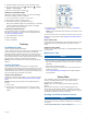
Installing the Left Pedal and Pedal Pod This procedure is for the Vector S system. 1 Apply a thin layer of grease on the pedal spindle threads À. 5 Tighten the cleat firmly to the shoe. NOTE: Garmin recommends torque of 4 to 6 lbf-ft. (5 to 8 Nm). Adjusting the Release Tension NOTICE Do not overtighten the release tension screw on the bottom of the pedal. The release tension should be adjusted equally for both pedals. 2 Insert the spindle into the crank arm Á. 3 Hand tighten the spindle.
1 Rotate the pedals a few times in order to activate Vector. 2 From the home screen, select > Sensors > > Sensor Details > Crank Length. 3 Enter the crank length, and select . Setting the Installation Angle Before you set the installation angles, you must set the Edge data fields to display power and cadence. 1 Go for a short ride on a trainer or on the road. 2 Ride until the cadence is nearly 70 rpm. 3 Accelerate smoothly to approximately 90 rpm.
Device Information Vector Device Care 2 Plug the small end of the USB cable into the USB port on the device. 3 Plug the large end of the USB cable into a computer USB port. 4 Go to www.garminconnect.com/start. 5 Follow the on-screen instructions. Garmin Connect You can connect with your friends on Garmin Connect. Garmin Connect gives you the tools to track, analyze, share, and encourage each other.
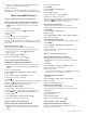
NOTE: The right pedal has a left-handed (reverse) thread. Water resistance IPX7 NOTICE Do not submerge or pressure wash the components. Radio frequency/ protocol 2.4 GHz ANT+ wireless communications protocol USB ANT Stick™ Specifications 3 Remove the pedal body. 4 While securely holding the spindle Á with a pedal wrench, use the 8 mm hex nut driver to remove the nut  and washer Ã. 5 Separate the cartridge from the spindle. 6 Remove the brass spacer ring Ä and dust seal Å.
7 Use a coin to twist the cover clockwise back into place, making sure the arrow points to locked. 8 Wait 10 seconds. After you replace the pedal pod battery, you must set the installation angle on your Edge (Setting the Installation Angle). Other Compatible Devices Edge 810 and 510 Device Instructions Pairing Vector with Your Edge 810 or 510 Device 1 Bring the Edge device within range (3 m) of the sensor. NOTE: Stay 10 m away from other ANT+ sensors while pairing. 2 Turn on the Edge device.
1 Bring the fēnix device within 3 m of the sensor. 2 3 4 5 6 NOTE: Stay 10 m away from other ANT+ sensors while pairing. Hold MENU. Select Settings > Sensors > Power. Rotate the crank arm a few times. Select your sensor. Select Status > On. When the sensor is paired with your fēnix device, the sensor status changes from Searching to Connected. Customizing the Data Fields 1 Hold MENU. 2 Select Settings > Sensors > Activity > Bike > Data Pages.
Power - 10s Avg.: The 10-second moving average of power output. Power - 30s Avg.: The 30-second moving average of power output. Power - 3s Avg.: The three-second moving average of power output. Power - Avg.: The average power output for the current activity. Power - IF: The Intensity Factor™ for the current activity. Power - kJ: The accumulated work performed (power output) in kilojoules. Power - Lap: The average power output for the current lap. Power - Lap Max.: The top power output for the current lap.
To upgrade your Vector system, go to www.garmin.com /vectorowner. • For 7 LED flashes, wait for the pedal pods and pedals to complete the software update. NOTE: Do not disconnect the pedal pod or remove the pedal pod batteries during a software update. Performing a Static Torque Test NOTICE The static torque test is intended for advanced cyclists and installation experts. This test is not required under normal circumstances to achieve good results with the Vector system.
Index B battery 2, 8 life 5 replacing 5 type 5 C calibrating 2, 3, 6, 7 cleaning the device 4 cleats 2 compatibility 9 customizing the device 3, 6, 7 cycling dynamics 3 D data storing 3, 4 transferring 3, 4 data fields 3, 6, 7 E Edge 2, 6 F fēnix 6 Forerunner 7 G Garmin Connect 3, 4 H history 3 sending to computer 3, 4 I installing 1, 2, 8 M memory 3 P pairing 2, 6–8 pedal pods 1, 2, 4, 5 pedals 1–4 platform center offset 3 power 3 power (force), meters 3 power phase 3 product registration 7 R reg
www.garmin.