
Instruction Manual


G1000 / GFC 700 System Maintenance Manual - 200/B200 Series King Air Page 6-19
190-00915-01 Revision 9
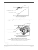
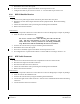
VIEW OF LEFT SIDE NOSE AVIONICS BAY
(NOT ALL ITEMS SHOWN FOR CLARITY)
COOLING FAN HOSE (TYP)
COOLING FAN
NOSE WHEEL WELL HOUSING
Figure 6-5, GIA Cooling Fan Installation
Configuration applicable to MDL 005-00421-00 Rev. 15 or previous FAA-approved
revisions
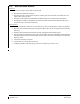
VIEW OF LEFT SIDE NOSE AVIONICS BAY
(NOT ALL ITEMS SHOWN FOR CLARITY)
COOLING FAN HOSE (TYP)
COOLING FAN
NOSE WHEEL WELL HOUSING
FAN INLET DUCT (IF INSTALLED)
P/N 115-00580-02
Figure 6-6, GIA Cooling Fan Inlet Duct Installation
Configuration applicable to MDL 005-00421-00 Rev. 16 or later FAA-approved
revisions, or modified per Garmin Service Bulletin 1375
Reinstallation:
1. Reinstallation of the avionics cooling fan is the reverse of the removal. Reference the Electrical
Equipment Install, Nose Bay drawing, listed in Table 1-2, for more details.
2. If further maintenance is not required, proceed to Section 8.