
Instruction Manual


Page 6-10 G1000 / GFC 700 System Maintenance Manual - 200/B200 Series King Air
Revision 9 190-00915-01
6.16 Configuration Modules
6.16.1 Configuration Module Removal & Replacement
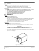
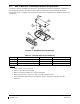
Configuration modules (Reference Figure 6-2 and Table 6-1, Item 1 shown below) are located in the
following LRU harness connector backshells (Item 6): GDU 1040A PFD, GRS 77 AHRS, GDC 74B Air
Data Computer, and the GEA 71 Engine/Airframe Unit. Additionally, the GRS 7800 has a different
configuration module that is located in the GRS 7800 connector backshell. Refer to Section 6.16.2 for the
GRS 7800 configuration module removal and replacement instructions. Refer to the Master Drawing
List, listed in Table 1-2, for specific installation drawings.
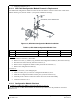
Figure 6-2, Configuration Module Installation
Table 6-1, Configuration Module Kit – 011-00979-00
Item Description Qty Needed Garmin Part
Number
1
Configuration Module PCB Board Assembly w/EEPROM & Temp
Sensor
1
012-00605-00 or -02
2 Spacer, Config Module 1 213-00043-00
3 Cable, 4-Conductor Harness 1 325-00122-00
4 Pins, #22 AWG (HD) 5 336-00021-00
Removal:
1. Disconnect connector from LRU.
2. Remove 2 screws (8) from cover (7) and remove cover.
3. Unplug connector from configuration module (1).
4. Remove configuration module.
Installation:
1. Inspect connector for damaged pins (4).
2. Place configuration module (1) in position.
3. Insert connector into configuration module (1).
4. Assembly of the connector is the reverse of disassembly.