
System Maintenance Manual


Page 4-14 G1000 / GFC 700 System Maintenance Manual - 200/B200 Series King Air
Revision 7 190-00915-01
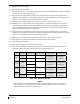
Table 4-8, Rear Fuselage and Empennage Visual Inspection Procedure
Item Description/Procedure Initials
Wi-fi Antenna
Inspect the external wi-fi antenna (if installed) for leading edge erosion and
condition of base seals.
To gain access for the following Inspections, refer to the servo installation drawings and the King Air 200 Series
Maintenance Manual, listed in Table 1-2.
Tail Wiring Harness
a) Inspect all exposed wire harness for chafing, damage, proper routing of wire
bundles and security of attachment in accordance with AC 43.13-1B,
Chapter 11, Section 8, Paragraph 11-96 and the Tail Wire Harness Routing
drawing, listed in Table 1-2. Pay particular attention to possible areas of
chaffing.
b) Verify security of aft bulkhead connectors
GFC 700 Equipment
a) Using a flashlight, inspect the servos, servo gearboxes, connectors, support
structure, and control cables to ensure that no corrosion, chaffing, cracks, or
other defects exist.
b) If GSM 86 servo gearboxes are installed, check that the retaining bolt for the slip
clutch cartridge is not damaged or loose.
c) Have an assistant manually move the control surfaces and elevator trim wheel
from stop to stop and visually observe the corresponding servo and control
cabling. Ensure there is no binding in the control cabling, and that the capstan
rotates freely.
d) Check the servo control cables in accordance with AC 43.13-1B, Chapter 7,
Section 8, Paragraph 7-149 to ensure no fraying, corrosion, or other damage
exists. If the condition of the cable is questionable, replace it with a new one.
e) Check the tension on the control cables. Refer to the respective servo
installation drawing listed in Table 1-2 for cable tension specifications
f) Ensure that each cable is correctly attached to the clamps.
g) Follow recommended checks for checking main control cables, following the
instructions in Chapter 27, Flight Controls, of the King Air 200 Series
Maintenance Manual, listed in Table 1-2.
h) Reinstall the access panels if no other maintenance is to be performed.
The GMU 44 units are mounted in the tailcone. To gain access, remove tailcone. Refer to King Air 200 Series
Maintenance Manual, listed in Table 1-2, for removal instructions.
GMU 44 (Qty 2)
a) For each GMU 44, do the following:
b) Remove the three Phillips screws holding the GMU access plate to the mounting
bracket. Be sure to use a non-magnetic screwdriver to avoid harming the GMU.
c) Carefully remove the assembly, taking care not to damage unit or wiring, and inspect
the GMU 44 and mounting plate.
d) Inspect the mounting hardware and GMU 44 for corrosion or other damage.
e) Inspect all exposed GMU wiring and ensure no chaffing, wear, or other damage exists
in accordance with AC 43.13-1B, Chapter 11, Section 8, Paragraph 11-96 and the
Tail Wire Harness Routing drawing, listed in Table 1-2. Pay particular attention to
possible areas of chaffing.
f) Reinstall the GMU 44.
Table 4-9, Lightning Strike Inspection Procedure
Item Description/Procedure Initials
GTP 59 OAT Probe
or Antenna
a) A post lightning strike inspection must be done for a suspected or actual lightning
strike to antennas or the OAT probes. Inspect antenna/probe and surrounding
installation to ensure that there is no structural damage around the areas where
lightning may have attached. If there is visible sign of damage to the probe or
antenna, then it should be replaced per section 6. Refer to the Hawker Beechcraft
Structural Inspection and Repair Manual listed in Table 1-2 for any aircraft structural
repairs.