
System Maintenance Manual


Page 6-16 G1000 / GFC 700 System Maintenance Manual - 200/B200 Series King Air
Revision 7 190-00915-01
6.27 Standby Attitude Indicator
Ensure the standby attitude indicator gyro is not spinning—this may take 10 minutes or longer after the
unit has been turned off. This unit is very delicate; handle like eggs. Refer to the 4200 Series Attitude
Indicator Installation Manual, listed in Table 1-2, for more handling instructions.
Removal:
1. Remove MFD per Section 6.1.
2. Disconnect the electrical connector of the standby attitude indicator.
3. Use a 0.060” 6-Spline wrench to remove the knob from the front of the standby attitude indicator.
4. Use a Phillips screwdriver to remove the three attachment screws from the front of the standby
attitude indicator.
5. Remove the standby attitude indicator.
Reinstallation:
1. Ensure the lighting control voltage switches on rear of unit are set for 28V.
28V
2. Reinstallation of the standby attitude indicator is the reverse of the removal. Reference the Main
Instrument Panel Installation drawing, listed in Table 1-2, for more details.
3. If further maintenance is not required, proceed to Section 8.
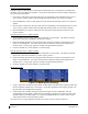
6.28 Nose Avionics Bay Cooling Fans
Removal:
1. Gain access into the nose avionics equipment bay.
2. Disconnect the cooling fan hoses from the cooling fan. Take necessary precautions to prevent
any foreign debris from entering the fan hoses during maintenance.
3. Disconnect the electrical connector of the cooling fan.
4. Use a Phillips screwdriver to remove the attachment screws from the cooling fan.
5. Remove the cooling fan.
Reinstallation:
1. Reinstallation of the avionics cooling fan is the reverse of the removal. Reference the Electrical
Equipment Install, Nose Bay drawing, listed in Table 1-2, for more details.
2. If further maintenance is not required, proceed to Section 8.
6.29 GDU Cooling Fans
Removal:
1. Remove the display associated with the cooling fan, per Section
6.1.
2. Disconnect the electrical connector of the cooling fan.
3. Use a Phillips screwdriver to remove the attachment screws from the cooling fan.
4. Remove the cooling fan.