
Pilot's Guide


190-00663-03 Rev. A
Garmin G1000 Pilot’s Guide for the Beechcraft C90A/GT/GTi
59
FLIGHT INSTRUMENTS
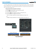
ATTITUDE INDICATOR
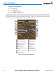
Attitude information is displayed over a virtual blue sky and brown ground with a white horizon line. The
Attitude Indicator displays the pitch, roll, and slip/skid information.
1
Roll Pointer
2
Roll Scale
3
Horizon Line
4
Aircraft Symbol
5
Land Representation
6
Pitch Scale
7
Slip/Skid Indicator
8
Sky Representation
9
Roll Scale Zero
Figure 2-8 Attitude Indicator
5
6
8
7
2
4
3
9
1
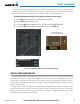
The horizon line is part of the pitch scale. Above and below the horizon line, major pitch marks and numeric
labels are shown for every 10˚, up to 80˚. Minor pitch marks are shown for intervening 5˚ increments, up to
25˚ below and 45˚ above the horizon line. Between 20˚ below to 20˚ above the horizon line, minor pitch marks
occur every 2.5˚. When the Garmin Synthetic Vision Technology (SVT) system is activated, the pitch scale is
reduced to 10˚ up and 7.5˚ down; refer to the Additional Features section.
The inverted white triangle indicates zero on the roll scale. Major tick marks at 30˚ and 60˚ and minor tick
marks at 10˚, 20˚, and 45˚ are shown to the left and right of the zero. Angle of bank is indicated by the position
of the pointer on the roll scale.
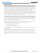
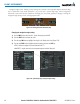
The Slip/Skid Indicator is the bar beneath the roll pointer. One bar displacement is equal to one ball
displacement on a traditional inclinometer. The indicator bar moves with the roll pointer and moves laterally
away from the pointer to indicate uncoordinated flight. Slip (inside the turn) or skid (outside the turn) is
indicated by the location of the bar relative to the pointer.
When the optional Garmin Electronic Stability and Protection (Garmin ESP
™
) system is available, additional
indications may appear on the pitch and roll scales; refer to the Additional Features and AFCS Sections for more
information about Garmin ESP.
Figure 2-9 Slip/Skid Indication