
Pilot's Guide


190-00663-03 Rev. A
Garmin G1000 Pilot’s Guide for the Beechcraft C90A/GT/GTi
357
HAZARD AVOIDANCE
3) Turn the small
FMS Knob to place the Bearing Line in the desired position. The location of the Bearing Line
becomes the center point of the Sector Scan.
4) Turn the large
FMS Knob to place the cursor in the SECTOR SCAN field.
5) Turn the small
FMS Knob to highlight the desired scan. Selecting ‘FULL’ enables a 120º scan.
6) If desired, readjust the Bearing Line as discussed previously to change the center of the Sector Scan.
7) Select the BRG Softkey again to remove the Bearing Line and cursor. The bearing reference is reset to 0º.
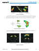
Figure 6-69 40˚ Sector Scan
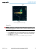
AntennA StABilizAtion
When radar antenna stabilization is enabled, the radar tilt is corrected for pitch and roll, and therefore is
kept steady with respect to an earth fixed reference. The commanded tilt angle is kept constant with respect
to the earth. When the stabilization is disabled, corrections are no longer made for pitch and roll, and the
radar tilt angle is kept constant with respect to the aircraft reference system.
Enabling/disabling antenna stabilization:
1) To activate or deactivate the antenna stabilization, select the MODE Softkey.
2) Select the STAB ON Softkey to activate antenna stabilization or select the STAB OFF Softkey to deactivate. The
current stabilization condition is shown in the upper right of the Weather Radar Page.
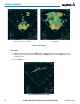
WeAtHeR AttenuAteD coloR HiGHliGHt (WAtcH™)
While in horizontal scan mode, this feature can be used as a tool to determine areas of possible inaccuracies
in displayed intensity due to weakening of the radar energy. This weakening is known as attenuation. The
radar energy weakens as it passes through areas of intense precipitation, large areas of lesser precipitation,
and distance. Issues with the radome also attenuates the radar energy. All these factors have an effect on the