
Pilot's Guide


190-00663-03 Rev. A
Garmin G1000 Pilot’s Guide for the Beechcraft C90A/GT/GTi
347
HAZARD AVOIDANCE
BASIC ANTENNA TILT SETUP
The following discussion is a simple method for setting up the weather radar antenna tilt for most situations.
It is not to be considered an all encompassing setup that works in all situations, but this method does provide
good overall parameters for the monitoring of threats. Ultimately, it is desired to have the antenna tilted so that
the bottom of the radar beam is four degrees below parallel with the ground. The following example explains
one way of achieving this.
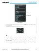
With the aircraft flying level, adjust the antenna tilt so ground returns are displayed at a distance that equals
the aircraft’s current altitude (AGL) divided by 1,000. For example, if the aircraft is at 14,000 feet, adjust the
tilt so the front edge of ground returns are displayed at 14 nautical miles. Note this antenna tilt angle setting.
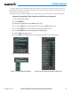
Now, raise the antenna tilt six degrees above this setting. The bottom of the radar beam is now angled down
four degrees from parallel with the ground.
PRACTICAL APPLICATION USING THE BASIC TILT SETUP
With the antenna tilt set as previously described, any displayed target return should be scrutinized when
flying at altitudes between 2,000 and 30,000 feet AGL. If the displayed target advances on the screen to within
five nautical miles of the aircraft, avoid it. This may be either weather or ground returns that are 2,000 feet or
less below the aircraft. Raising the antenna tilt 4 degrees can help separate ground returns from weather returns
in relatively flat terrain. This aligns the bottom of the radar beam parallel with the ground. Return the antenna
tilt to the previous setting after a few sweeps.
If the aircraft is above 29,000 feet, be cautious of any target return that gets to within 30 nautical miles. This
is likely a thunderstorm that has a top high enough that the aircraft cannot fly over it safely.
If the aircraft altitude is 15,000 feet or lower, setting the displayed range to 60 miles may be more helpful.
Closely monitor anything that enters the display.
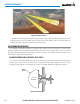
Also, after setting up the antenna tilt angle as described previously, ground returns can be monitored for
possible threats. The relationship between antenna tilt angle, altitude, and distance is one degree of tilt equals
100 feet of altitude for every one nautical mile.
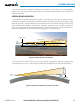
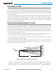
Vertical Change of Radar Beam (feet)
Change in Antenna Tilt
10 nm
0
1000
2000
3000
4000
1000
2000
3000
4000
-1°
0°
-2°
-3°
-4°
+1°
+2°
+3°
+4°
Figure 6-58 Vertical Change in Radar Beam per Nautical Mile
Therefore, with the antenna tilt set so that the bottom of the beam is four degrees below parallel with
the ground, a target return at 10 nm is approximately 4,000 feet below the aircraft; at 20 nm, 8,000 feet;
at 50 nm, 20,000 feet. In other words, at this tilt setting, a ground return (such as a mountain peak) being