
Pilot's Guide


190-00663-03 Rev. A
Garmin G1000 Pilot’s Guide for the Beechcraft C90A/GT/GTi
343
HAZARD AVOIDANCE
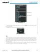
Both systems use colors to identify the different echo intensities, but the colors are not interchangeable.
Airborne color radar values used by Garmin Airborne Color Weather Radar should not be confused with
NEXRAD radar values.
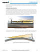
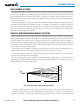
ANTENNA BEAM ILLUMINATION
The radar beam is much like the beam of a spotlight. The further the beam travels, the wider it becomes.
The radar is only capable of seeing what is inside the boundaries of the beam. The figure below depicts a radar
beam’s characteristics. The figure illustrates vertical dimensions of the radar beam, although the same holds
true for the horizontal dimensions. In other words, the beam is as wide as it is tall. Note that it is possible to
miss areas of precipitation on the radar display because of the antenna tilt setting. With the antenna tilt set
to zero in this illustration, the beam overshoots the precipitation at 15 nautical miles.
Figure 6-53 Radar Beam from a 12 inch Antenna
0
80
Altitude (x1000 ft.)
30 0 45 60 75 90
Range (nautical miles)
Half Power at Beam Sidelobes
Antenna at Zero Tilt
18,000 ft.
18,000 ft.
Max Power at Beam Center
15
8°
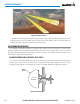
The curvature of the earth can also be a factor in missing areas of precipitation, especially at range settings
of 150 nautical miles or more. Here the beam overshoots the precipitation at less than 320 nautical miles.
320 nm
Figure 6-54 Radar Beam in Relation to the Curvature of the Earth