
Installation Instructions


Item Garmin Wire
Function
Garmin Wire
Color
NMEA 0183
Device Wire
Function
Ï
TxA (+) Gray Rx
Ð
TxB (-) Pink N/A
• If the NMEA 0183 device has only one input (receive, Rx)
wire (no A, B, +, or -), you must leave the pink wire
unconnected.
• If the NMEA 0183 device has only one output (transmit, Tx)
wire (no A, B, +, or -), you must connect the orange/white
wire to ground.
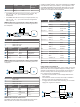
NMEA 0183 Device Connected with a Single Receive Wire
In this example, the NMEA 0183 device is receiving data from
the chartplotter.
Item Description
À
Power source
Á
Power cable
Â
NMEA 0183 device
Ã
NMEA 0183 cable
Item Garmin Wire
Function
Garmin Wire
Color
NMEA 0183 Device
Wire Function
Ê
Power Red Power
Ë
Power ground Black Power ground
Ì
Data ground Black Data ground
Í
TxA (+) Gray RxA
Î
TxB (-) Pink N/A
NMEA 0183 Device Connected with a Single Transmit Wire
In this example, the NMEA 0183 device is sending data to the
chartplotter.
Item Description
À
Power source
Á
Power cable
Â
NMEA 0183 device
Ã
NMEA 0183 cable
Item Garmin Wire
Function
Garmin Wire
Color
NMEA 0183 Device
Wire Function
Ê
Power Red Power
Ë
Power ground Black Power ground
Ì
Data ground Black Data ground
Í
RxB (-) Orange/white N/A
Î
RxA (+) White TxA (+)
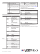
NMEA 0183 with Audio Cable Pinout
The NMEA 0183 with audio cable includes bare wires and an
RCA connector for an audio out connection to a stereo,
including FUSION
®
stereos. This pinout information is for NMEA
0183 with audio cable (010-12390-21). The chartplotter is also
compatible with NMEA 0183 threaded cables that do not have
audio connections (010-11425-02 and 010-11425-05). These
cables are not included with the chartplotter.
Port Wire Function Wire Color Pin Number
Input port 1 RX/A (+) White
RX/B (-) Orange/white
Input port 2 RX/A (+) Brown
RX/B (-) Brown/white
Input port 3 RX/A (+) Violet
RX/B (-) Violet/white
Input port 4 RX/A (+) Black/white
RX/B (-) Red/white
Output port 1 TX/A (+) Gray
TX/B (-) Pink
Output port 2 TX/A (+) Blue
TX/B (-) Blue/white
N/A Audio Common Blue/red
N/A Audio Right Channel Red
N/A Audio Left Channel White
N/A Alarm Yellow
N/A Accessory on Orange
N/A Ground (shield) Black
N/A Spare N/A
Lamp or Horn Connections
The device can be used with a lamp, a horn, or both, to sound or
flash an alert when the chartplotter displays a message. This is
optional, and the alarm wire is not necessary for the device to
function normally. When connecting the device to a lamp or
horn, observe these considerations.
• The alarm circuit switches to a low-voltage state when the
alarm sounds.
• The maximum current is 100 mA, and a relay is needed to
limit the current from the chartplotter to 100 mA.
• To toggle visual and audible alerts manually, you can install
single-pole, single-throw switches.
5