
Installation instructions


Bleeding the Hydraulics
NOTICE
This is a general procedure for bleeding a hydraulic steering
system. Refer to the instructions provided by the manufacturer
of the steering system for more-specific information about
bleeding the system.
Before you bleed the hydraulic system, you should verify that all
hose connections are complete and fully tightened.
1
Select an option:
• If the helm reservoir contains insufficient fluid, fill it as
needed.
• If the helm reservoir contains excess fluid, remove the
excess to avoid fluid overflow during the bleeding process.
2
Insert a bypass hose between the cylinder bleed ports.
TIP: If you use a clear plastic hose for this bypass, you can
observe air bubbles during the bleeding processes.
3
Manually steer the helm fully to port.
4
Open both bypass valves at the cylinder fittings.
5
Open the bypass valve on the pump manifold.
6
Manually turn the helm slowly to port over three minutes.
TIP: You can stop turning when you no longer see air moving
through the bypass hose.
7
Turn on the autopilot system and disable the Shadow Drive.
You can refer to the autopilot system documentation for more
information on disabling the Shadow Drive.
8
Hold (port) on the helm control for at least 10 seconds.
TIP: You can stop holding when you no longer see air
moving through the bypass hose.
9
Close both bypass valves at the cylinder fittings.
10
Close the bypass valve on the pump manifold.
11
If necessary, add fluid to the helm reservoir.
12
Repeat steps 3 through 11 for the starboard side.
13
Hold (port) on the helm control until steering stops and
Hydraulic Pump Stall is shown on the helm control.
14
Hold (starboard) on the helm control until steering stops
and Hydraulic Pump Stall is shown on the helm control.
15
Select an option:
• If Hydraulic Pump Stall is not shown within 2 to 3
seconds after the cylinder stops, repeat steps 1-15 to
bleed the system again.
• If Hydraulic Pump Stall is shown within 2 to 3 seconds
after the cylinder stops, the system bleed completed
successfully.
After hydraulic bleeding is complete, you can re-enable the
Shadow Drive.
Corrosion Blocker
NOTICE
To ensure long life of all parts, apply corrosion blocker to the
pump at least twice yearly.
A marine-rated corrosion blocker should be applied to the pump
after all hydraulic and electrical connections are made and the
hydraulic system has been bled.
Installing a Garmin Rudder Feedback Sensor
Installing a rudder feedback sensor, such as the GRF
™
10 (sold
separately), is not necessary for the autopilot to function
correctly, but doing so will increase performance, provide an on-
screen rudder indication, and extend the life of the SmartPump.
Follow the installation instructions provided with your GRF
rudder feedback sensor to connect it to your rudder control
and autopilot system.
Connecting the CCU
1
Route the connector end of the CCU cable to the SmartPump
and make the connection.
2
Route the orange and blue wires from the bare-wire portion
of the CCU cable to the location where you plan to install the
alarm (Installing the Alarm).
If the cable is not long enough, extend the appropriate wires
with 0.08 mm
2
(28 AWG) wire.
3
Route the brown and black wires from the bare-wire portion
of the CCU cable to the location where you plan to install the
Shadow Drive (Installing the Shadow Drive).
If the cable is not long enough, extend the appropriate wires
with 0.08 mm
2
(28 AWG) wire.
Installing the Shadow Drive
Connecting the Shadow Drive to the Hydraulic System
Before you can install the Shadow Drive, you must select a
location at which to connect the Shadow Drive to the hydraulic
steering of your boat (Shadow Drive
™
Mounting Considerations).
For further assistance, consult the hydraulic-layout diagrams
(Hydraulic Layouts).
Use hydraulic connectors (not included) to install the Shadow
Drive in the appropriate hydraulic line.
Connecting the Shadow Drive to the CCU
1
Route the bare-wire end of the CCU cable to the Shadow
Drive.
If the cable is not long enough, extend the appropriate wires
with 28 AWG (0.08 mm²) wire.
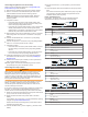
2
Connect the cables, based on this table.
Shadow Drive Wire Color CCU Cable Wire Color
Red (+) Brown (+)
Black (-) Black (-)
3
Solder and cover all bare-wire connections.
Installing the Alarm
Before you can mount the alarm, you must select a mounting
location (Alarm Mounting and Connection Considerations).
1
Route the alarm cable to the bare-wire end of the CCU cable.
If the cable is not long enough, extend the appropriate wires
with 28 AWG (0.08 mm
2
) wire.
2
Connect the cables, based on this table.
Alarm Wire Color CCU Cable Wire Color
White (+) Orange (+)
Black (-) Blue (-)
3
Solder and cover all bare-wire connections.
4
Secure the alarm with cable ties or other mounting hardware
(not included).
NMEA 2000 and the Autopilot Components
NOTICE
If you have an existing NMEA 2000 network on your boat, it
should already be connected to power. Do not connect the
NMEA 2000 power cable to an existing NMEA 2000 network,
because only one power source should be connected to a
NMEA 2000 network.
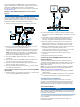
You can connect the helm control and the CCU through an
existing NMEA 2000 network. If you do not have an existing
NMEA 2000 network on your boat, all the parts needed to build
one are supplied in the autopilot package (Building a Basic
NMEA 2000 Network for the Autopilot System).
To use advanced features of the autopilot, optional NMEA 2000
devices, such as a GPS device, can be connected to the NMEA
2000 network.
8