LOG OF REVISIONS Page Revision Number Date Number Description FAA Approved 1 05/15/2014 All Complete Supplement See page 1 190-01527-16 Rev 1 Page 2 of 25 RFMS, Eurocopter EC130 B4 G500H System FAA APPROVED
TABLE OF CONTENTS SECTION 1. GENERAL ....................................................................... 5 1.1 System Description ....................................................... 5 1.2 System Power Sources .................................................. 6 1.3 Navigation Sources ....................................................... 6 1.4 Helicopter Synthetic Vision Technology (Optional) .... 6 1.5 Audio Panel .................................................................. 8 1.
SECTION 4. NORMAL PROCEDURES ........................................... 22 4.1 PFD Knob & PFD Soft Keys ...................................... 22 4.2 MFD Knobs & MFD Soft Keys .................................. 22 4.3 Helicopter Synthetic Vision Technology (HSVT) ...... 23 4.4 HSVT Terrain ............................................................. 23 4.5 Altitude Alerter ........................................................... 23 SECTION 5. PERFORMANCE ................................................
SECTION 1. GENERAL 1.1 System Description The G500H Flight Display System consists of a Primary Flight Display (PFD) and Multi- Function Display (MFD) housed in a single Garmin Display Unit (GDU 620), an Air Data Computer (GDC 74H ADC) and Attitude and Heading Reference Systems (GRS 77H AHRS). The G500H interfaces with a Garmin GNS 400W, 500W, or 480 series GPS/WAAS navigator and an audio panel.
pilot’s normal instrument scan and must be utilized if the PFD data is in question. 1.2 System Power Sources The G500H system depends on electrical power to function. The Garmin Display Unit (GDU), Attitude and Heading Reference System (AHRS), and Air Data Computer (ADC) are connected to the aircraft main bus. The major components of the G500H are circuit breaker protected with pushpull type circuit breakers available to the pilot.
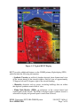
Figure 1-2- Typical HSVT Display HSVT provides additional features on the G500H primary flight display (PFD) which include the following information: • Synthetic Terrain; an artificial, database derived, three dimensional view of the terrain ahead of the aircraft within a field of view of approximately 25 degrees left and 25 degrees right of the aircraft heading. • Obstacles; obstacles such as towers, including buildings that are within the depicted synthetic terrain field of view.
• Horizon Line; a white line indicating the true horizon is always displayed on the SVT display. • Horizon Heading; a pilot selectable display of heading marks displayed just above the horizon line on the PFD. • Airport Signs; pilot selectable “signposts” displayed on the synthetic terrain display indicating the position of nearby airports that are in the G500H database. • Runway Highlight; a highlighted presentation of the location and orientation of the runway(s) at the destination airport.
1.7 Traffic Display and Control (Optional) The G500H Flight Display System can display traffic from various sources including TIS data from the Garmin GTX Series Mode-S Transponders or TAS data from various active traffic awareness systems. The information from these systems is displayed on and controlled through the MFD. Traffic shown on the display may or may not have traffic alerting available. The display of traffic is an aid to visual acquisition and is not to be utilized for aircraft maneuvering.
The upper Secure Digital (SD) data card slot is typically vacant as it is used for software maintenance and navigational database updates. The lower data card slot should contain a data card with the system’s terrain / obstacle information and optional data including Safe Taxi, FliteCharts and ChartView electronic charts. 1.13 System Description Reference Garmin G500H PFD/MFD System Cockpit Reference Guide P/N 190-01150-03 for basic operational aspects of the system.
G500H Avionics System Magnetometer GMU 44 Equipment Installed per this STC AHRS GRS 77H GDU 620 PFD/MFD Air Data Computer GDC 74H Temperature Probe GTP 59 Audio Panel Various models No. 1 GPS/WAAS Navigator and/or VOR/Localizer/GS GNS 400W/500W series or GNS 480 (required) Traffic Various Models (optional) No.
SECTION 2. LIMITATIONS 2.1 Types of Operation Rotorcraft equipped with the G500H Flight Display System are limited to VFR ONLY operations in accordance with Title 14 Code of Federal Regulations Part 91 and Part 135. 2.2 Cockpit Reference & Pilot’s Guides Garmin G500H Cockpit Reference Guide P/N 190-01150-03, Revision A or later appropriate revision must be immediately available to the flight crew. 2.
latitude in all longitudes. The obstacle database contains data for obstacles, such as towers, that pose a potential hazard to aircraft. It is very important to note that not all obstacles are necessarily charted and therefore may not be contained in the obstacle database. Coverage of the obstacle database includes the United States and Europe. This database is updated on a 56-day cycle. The Garmin SafeTaxi database contains detailed airport diagrams for selected airports.
with a placard for determining maximum airspeed based on altitude; that placard remains as the means to determine maximum airspeed. 2.8 Navigation Angle The GDU 620 Navigation Angle can be set to either True or Magnetic on the AUX page. The Navigation Angle defines whether the GDU 620 headings are referenced to True or Magnetic North. The Navigation Angle set in the GDU 620 must match that which is set on the GNS navigators. 2.9 Course Pointer Auto Slewing The G500H HSI will auto slew, i.e.
2.13 Traffic Display Traffic may be displayed on the G500H System from TIS or TAS systems. These systems are capable of providing traffic monitoring and alerting to the pilot. Traffic shown on the display may or may not have traffic alerting available. The display of traffic is an aid to visual acquisition and is not to be utilized for aircraft maneuvering.
2.14 Equipment Requirements Table 2-3 lists the minimum fully functional G500H System Elements required for VFR flight operations: Table 2-3 Equipment Requirements Number Installed VFR Primary/ Multi Flight Display 1 0 Attitude/ Heading Unit (AHRS) 1 0 Air Data Computer (ADC) 1 0 Magnetometer 1 0 Standby Altimeter 1 1 Standby Airspeed 1 1 Magnetic Compass 1 1 GNS 400W, 500W or 480 series navigator 1 0 Equipment 2.
SECTION 3. EMERGENCY PROCEDURES 3.1. Loss of Electrical Power In the event of a total loss of electrical power, the G500H system will cease to operate and the pilot must utilize the standby instruments and visual references to fly the aircraft 3.2. Malfunction Indications and Procedures These procedures supersede those presented as markings or placards, or documented in the aircraft’s FAA approved Rotorcraft Flight Manual as a result of the installation of the G500H system.
adjusted by the PFD knob set to CRS. Under this condition, the pilot must use the standby compass. Air Data Computer (ADC) Failure Complete loss of the Air Data Computer is indicated by a red X and yellow text over the airspeed, altimeter, vertical speed, TAS and OAT displays. Some derived functions, such as true airspeed and wind calculations, will also be lost. 1. Use Standby Airspeed and Altimeter, visual references, and secondary cues.
NOTE: The G500H Cockpit Reference Guide and the G500H Pilot’s Guide contain detailed descriptions of the annunciator system and all warnings, cautions and advisories.
TERRAIN Visually acquire the terrain and avoid SVT Terrain has determined that a nearby obstacle poses a collision hazard. OBSTACLE Visually acquire the obstacle and avoid SVT Terrain has determined that a nearby obstacle poses a collision hazard. Table 3-2 Caution Annunciations – Yellow Annunciation Pilot Action Cause Limit rotorcraft bank to less than 10 degrees as AHRS Aligns Attitude and Heading Reference System is aligning. Keep attitude level using outside references.
Cockpit Reference for the appropriate pilot or service action. Optional Annunciations The following tables show the color and significance of other annunciation messages which may appear. Table 3-4 Advisories – Yellow Annunciation EFIS FAN FAIL Pilot Action Cause No action required. The cooling fan is optional and not required for G500H operation. The cooling fan installation is not reaching the designed fan speed or has failed.
SECTION 4. NORMAL PROCEDURES Refer to the Garmin G500H PFD/MFD System Cockpit Reference Guide P/N 19001150-03 or G500H Pilot’s Guide P/N 190-01150-02, for detailed operating procedures. This includes all Primary Flight Display and Multi-Function Display information. Although intuitive and user friendly, the G500H PFD/MFD System requires a reasonable degree of familiarity to avoid becoming too engrossed at the expense of situational awareness.
Keys at the bottom of the display allow for the rapid selection of pre-defined functions to be performed on each page. The soft keys operate by press and release. More detailed configuration is typically available by pressing the MENU button, located on the right side of the display. Pressing and holding down the CLR key will display the main map page on the MFD. Details of the functions available on the MFD are explained in the Garmin G500H Cockpit Reference Guide defined in Paragraph 1.1. 4.
SECTION 5.
SECTION 6. WEIGHT AND BALANCE - No Change from the Basic Flight Manual.