
Instruction Manual


G500H Flight Display System 190-01150-11 Rev. 2
Instructions for Continued Airworthiness Bell 206A/B Series Page 18 of 19
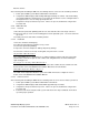
2.8 Diagrams
Rotorcraft specific LRU locations and wire routing diagrams are contained in the Garmin Reference
Publications listed in Section 2.1 of this document. Point to point wiring diagrams are in Appendix D of
the G500H STC Installation Manual. Refer to the G500H Post-Installation Checkout Log retained in the
rotorcraft permanent records for a list of the interfaced equipment and port configurations.
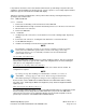
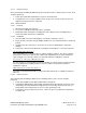
2.9 Special Inspection Requirements
2.9.1
Post-Lightning Strike Inspection
In the event of a suspected or actual lightning strike to the aircraft, the GTP 59
OAT Probe and its associated installation shall be inspected.
The probe and the surrounding installation shall be inspected to ensure that there is no structural
damage around the areas where lightning may have attached. If there is visible sign of damage to the
probe then it must be replaced.
Verify that OAT is displayed on the GDU 620 PFD normally.
2.10 Application of Protective Treatments
None, N/A.
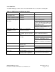
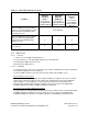
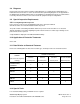
2.11 Data Relative to Structural Fasteners
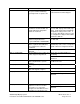
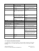
Refer to the following table for data on the location, type, and torque values for structural fasteners.
Location
(seeGeneralArrangement
Drawing)
FASTENERTYPEANDTORQUE
6‐32Screw
12‐15inch‐pounds
8‐32Screw
12‐15inch‐pounds
10‐32Screw
22‐25inch‐pounds
NUT,5/16",HEX,SKIRT
100±20inch‐pounds
InstrumentPanel,
Instruments
X X
GDU620 X
GRS77H XX
GDC74H X X
GMU44 X X
GTP59 X
2.12 Special Tools
For electrical bonding testing, a milliohm meter is required.