
Rotorcraft Flight Manual Supplement


RFMS Garmin G500H as installed in Bell 206A 190-01150-12 Rev. B
FAA APPROVED Page 17 of 24
GENERAL INFORMATION
Garmin G500H Flight Display System
The G500H Flight Display System consists of a Primary Flight Display (PFD)
and Multi-Function Display (MFD) housed in a single Garmin Display Unit
(GDU 620), an Air Data Computer (GDC 74H ADC) and Attitude and Heading
Reference Systems (GRS 77H AHRS). The G500H interfaces with a Garmin
GNS 400W, 500W, or 480 series GPS/WAAS navigator and an audio panel.
Optionally, the G500H may interface with other systems installed in the
rotorcraft including a Garmin GTX330 transponder, TAS traffic system, GDL
69(A) satellite data link, video sources, and GSR 56 Iridium data link.
The primary function of the PFD is to provide attitude, heading, air data and
navigation information (from GNS units) to the pilot. The primary function of
the MFD is to display supplemental data including mapping, terrain, video,
charts, and flight plan information.
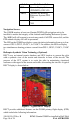
Figure 4 - GDU 620 Displays
The standby instruments (airspeed, altimeter and magnetic compass) are
completely independent from the PFD and will continue to operate in the event
the PFD is inoperative. These standby instruments should be included in the
pilot’s normal instrument scan and must be utilized if the PFD data is in
question.
System Power Sources
The G500H system depends on electrical power to function. The Garmin
Display Unit (GDU), Attitude and Heading Reference System (AHRS), and Air
Data Computer (ADC) are connected to the aircraft main bus.
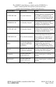
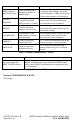
The major components of the G500H are circuit breaker protected with reset-
able type circuit breaker available to the pilot. These breakers are located on the
overhead circuit breaker panel and are labeled as follows: