LOG OF REVISIONS Page Revision Number A Origina l Date May 5, 2010 No. All Description Complete Supplement FAA Approved Seyed-Joussef Hashemi Mgr. Flt. Test Br., ANM160L Federal Aviation Administration Los Angeles Aircraft Certification Office Transport Airplane Directorate Date: May 5, 2010 B November 14, 2014 5 Table 1-1: GDU software was 4.00 See page 1 GRS 77H software was 3.50 GDC 74H software was 3.06 5 Table 1-2: Added GTN 6XX and 7XX along with note 9 1.
LOG OF REVISIONS Page Revision Number Date No. 23 Description FAA Approved Updated Figure 6 RFMS Garmin G500H as installed in Bell 206A FAA APPROVED 190-01150-12 Rev.
Table of Contents SECTION 2. OPERATING LIMITATIONS .................................................. 6 2.1 2.2 2.3 2.4 2.5 2.6 2.7 2.8 2.9 2.10 2.11 2.12 2.13 2.14 2.15 TYPES OF OPERATION ........................................................................... 6 COCKPIT REFERENCE & PILOT’S GUIDES .............................................. 6 SYSTEM SOFTWARE REQUIREMENTS..................................................... 6 DATABASES ..................................................................
Traffic Display and Control (Optional) ......................................................20 XM Data link (Optional) .............................................................................20 Video Input (Optional) ................................................................................20 Iridium Data link (Optional).......................................................................20 Radar Altimeter (Optional) .........................................................................
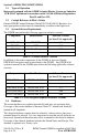
Section 2. OPERATING LIMITATIONS 2.1 Types of Operation Rotorcraft equipped with the G500H Avionics Display System are limited to VFR ONLY operations in accordance with 14 Code of Federal Regulations Part 91 and Part 135. 2.2 Cockpit Reference & Pilot’s Guides Garmin G500H Cockpit Reference Guide P/N 190-01150-03, Revision A or later appropriate revision must be immediately available to the flight crew. 2.
The Garmin SafeTaxi database contains detailed airport diagrams for selected airports. These diagrams aid in following air traffic control instructions by accurately displaying the aircraft position on the map in relation to taxiways, ramps, runways, terminals, and services. This database is updated on a 56-day cycle. The Garmin FliteCharts database contains procedure charts for the coverage area purchased. This database is updated on a 28-day cycle.
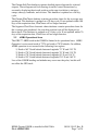
2.6 AHRS Operation The GRS 77 AHRS used in the G500H uses GPS data, air data, and magnetometer inputs to improve availability. The GRS 77 will operate in reversionary modes that do not require these inputs. When operating in no magnetometer or no magnetometer/no air data modes rapid pitch or roll movements may result in temporary loss of attitude indication. 2.7 Maximum Airspeed The airspeed markings on the G500H PFD match those on the standby indicator regardless of operating altitude.
2.12 Datalinked Weather Display XM weather data is provided by an optional GDL 69 interface. The weather information display on the MFD of the G500 is limited to supplemental use only and may not be used in lieu of an official weather data source. 2.13 Traffic Display Traffic may be displayed on the G500H System from TIS or TAS systems. These systems are capable of providing traffic monitoring and alerting to the pilot. Traffic shown on the display may or may not have traffic alerting available.
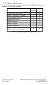
2.15 Equipment Requirements Table 1-3 below lists the minimum fully functional G500H System Elements required for VFR flight operations: Equipment Number installed VFR Primary/Multi Flight Display 1 0 Attitude / Heading Unit (AHRS) 1 0 Air data computer (ADC) 1 0 Magnetometer (GMU) 1 0 Standby Altimeter 1 1 Standby Airspeed 1 1 Magnetic Compass 1 1 GTN 6XX, GTN 7XX, GNS 400W, 500W, or 480 series navigator 1 0 Table 1-3 G500H Equipment Requirements 190-01150-12 Rev.
Section 3. OPERATING PROCEDURES Refer to the Garmin G500H PFD/MFD System Cockpit Reference Guide P/N 190-01150-03 or G500H Pilot’s Guide P/N 190-01150-02, for detailed operating procedures. This includes all Primary Flight Display and Multi-Function Display information. Although intuitive and user friendly, the G500H PFD/MFD System requires a reasonable degree of familiarity to avoid becoming too engrossed at the expense of situational awareness.
3.1.2 MFD Knobs & MFD Soft Keys The MFD controls are adjacent to and beneath the MFD display. The rotary knobs are used to scroll through various pages/page groups of the MFD. Pressing the knob will activate a cursor and allow for the user to enter data and manipulate settings. Soft keys at the bottom of the display allow for the rapid selection of pre-defined functions to be performed on each page. The soft keys operate by press and release.
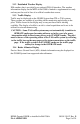
3.2.3 AHRS Failure A failure of the Attitude and Heading Reference System (AHRS) is indicated by a removal of the sky/ground presentation, a red X over the attitude indicator, and a yellow “AHRS FAILURE” shown on the PFD. A heading failure will also be indicated. 1. Use visual references for aircraft control 2. Set course datum using CRS selection of the PFD knob The Attitude, Heading and Reference System (AHRS) requires at least one GPS or air data input to function properly.
If GPS position information from the GPS WAAS navigator is not valid, the own-ship icon on the MFD is removed and “NO GPS POSITION” text is overlaid on the MFD moving map. The system will annunciate a loss of integrity, “LOI” on the HSI. The LOI annunciation will be colored yellow and the HSI needle will flag. The pilot should select an alternate navigation source (via CDI key or 1-2 key). Pressing the CDI soft key will change the HSI navigation source.
NOTE The G500H Cockpit Reference Guide and the G500H Pilot’s Guide contain detailed descriptions of the annunciator system and all warnings, cautions and advisories. Annunciation Pilot Action Cause Use visual references Display system is not receiving attitude reference information from the AHRS; accompanied by the removal of sky/ground presentation and a red X over the attitude area.
Annunciation Pilot Action Cause AHRS Aligning – Keep Wings Level Limit rotorcraft bank to less than 10 degrees as AHRS Aligns Attitude and Heading Reference System is aligning. Keep attitude level using outside references. AHRS will not align if bank angle remains over 10 degrees. NO GPS POSITION If the system is configured with dual GPS, press the 1-2 button GPS data on the selected system is no longer valid. The Moving Map and associated data are not updating.
GENERAL INFORMATION Garmin G500H Flight Display System The G500H Flight Display System consists of a Primary Flight Display (PFD) and Multi-Function Display (MFD) housed in a single Garmin Display Unit (GDU 620), an Air Data Computer (GDC 74H ADC) and Attitude and Heading Reference Systems (GRS 77H AHRS). The G500H interfaces with a Garmin GNS 400W, 500W, or 480 series GPS/WAAS navigator and an audio panel.
Label Unit Controlled PFD Garmin Display Unit (PFD/MFD), GDU 620 AHRS Attitude and Heading Reference System, GRS 77H ADC Air Data Computer, GDC 74H Navigation Sources The G500H requires at least one Garmin GPS/WAAS navigation unit to be installed to ensure the integrity of the Attitude and Heading Reference System. The AHRS will still operate in reversionary mode if all GPS sources fail, and the PFD attitude display will still be presented.
• Synthetic Terrain; an artificial, database derived, three dimensional view of the terrain ahead of the aircraft within a field of view of approximately 25 degrees left and 25 degrees right of the aircraft heading. • Obstacles; obstacles such as towers, including buildings that are within the depicted synthetic terrain field of view. • Flight Path Marker (FPM); an indication of the current lateral and vertical path of the aircraft.
GTN 6XX or 7XX Series Navigator GNS 400W or 500W Series Navigator Traffic Display and Control (Optional) The G500H Avionics Display System can display traffic from various sources including TIS data from the Garmin GTX Series Mode-S Transponders or TAS data from various active traffic awareness systems. The information from these systems is displayed on and controlled through the MFD.
The upper Secure Digital (SD) data card slot is typically vacant as it is used for software maintenance and navigational database updates. The lower data card slot should contain a data card with the system’s terrain / obstacle information and optional data including Safe Taxi, FliteCharts and ChartView electronic charts. RFMS Garmin G500H as installed in Bell 206A FAA APPROVED 190-01150-12 Rev.
SYSTEM DESCRIPTION Reference Garmin G500H PFD/MFD System Cockpit Reference Guide P/N 190-01150-03 for basic operational aspects of the system. For a complete detailed explanation of all the G500H’s capabilities see the G500H Pilot’s Guide P/N 190-01150-02. Pitot-Static System The pitot-static system supplies pitot-static pressure to the GDC 74H, standby altimeter, and standby airspeed indicator. 190-01150-12 Rev.
System Block Diagram G500H Avionics System Magnetometer GMU 44 Equipment Installed per this STC AHRS GRS 77H GDU 620 PFD/MFD Air Data Computer GDC 74H Temperature Probe GTP 59 Audio Panel Various models No. 1 GPS/WAAS Navigator and/or VOR/Localizer/GS GTN 6XX/7XX, GNS 400W/ 500W series or GNS 480 (required) Traffic Various Models (optional) No.
DEFINITIONS The following terminology is used within this document: ADC: Air Data Computer AHRS: Attitude & Heading Reference System BARO: Barometric Pressure BRG: Bearing CDI: Course Deviation Indicator CRS: Course FPM: Flight Path Marker GDU: Garmin Display Unit GPS: Global Positioning System HDG: Heading HSI: Horizontal Situation Indicator ILS: Instrument Landing System LDA: Localizer Directional Aid LOC: Localizer LOC BC: Localizer Backcourse MFD: Multi Function Display PFD: Primary Flight Display SD: S