
Instruction Manual


G500H Flight Display System 190-01150-20 Rev. 1
Instructions for Continued Airworthiness Bell 206L Series Page 7 of 19
1
2
3
4
5
6
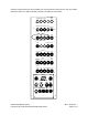
The installed G500H equipment can be accessed as described below:
1. GDU 620: FS38.6, WL 43.3 Access or remove by removing the six screws in the bezel of the
GDU 620.
2. GDC 74H: FS32.8, WL 37.6 Access or remove by lowering instrument console at its hinge
point and removing the top instrument console cowling.
3. GRS 77H: FS62.0, WL20.0 (Secondary location) Access or remove by removing the cushion
from the co-pilots seat and the panel on top of the seat pedestal.
4. GRS 77H: FS172.8, WL54.7 (Primary location) Access or remove by opening the baggage
compartment and removing the access panel located on the ceiling of the baggage
compartment.
5. GMU 44: FS219.6, WL59.5 (Primary location) Access or remove by opening the baggage
compartment, removing the screws on the aft wall of the baggage compartment which hold
in place the plastic baggage compartment extension.
6. GMU 44: FS243.0, WL64.9 (Secondary location) Access or remove by removing the bolts
from the access panel on the pilots side of the aircraft at the juncture of the tail boom and
fuselage.
2.2.1 Weight and Balance Information
Weight and Balance Bell 206 L Moment arm (IN) Location
Item Part Number Weight (LB) Longitudinal Lateral Primary Secondary
1 011-01264-50 GDU 620 (Unit Only) 6.38
38.6 6.3
GDU 620 (Installed with rack and
connector)
7.04
2 011-00882-11 GDC 74H (Unit Only) 1.70
GDC 74H (Installed with connector) 1.92
3 011-00868-20 GRS 77H (Unit Only) 2.80
GRS 77H (Installed with rack and
connector)
3.46
4 011-00870-10 GMU 44 (Unit Only) 0.35 219.6 0.0
GMU 44 (Installed with rack and
connector)
0.50 219.6 0.0
GMU 44 (Unit Only) 0.35 243.0
GMU 44 (Installed with rack and
connector)
0.50 243.0
[1] A rotorcraft weight and balance is required after installation of the G500H system. Refer to STC
installation manual P/N 190-01150-06 for additional information, including overall size and center of
gravity location of all LRUs.
[2] The longitudinal arm is measured in terms of the fuselage station (FS) number.
[3] The lateral arm is measured in terms of the butt line (BL). The centerline of the helicopter is BL0.00.
The moment arms to the left side (looking forward) are negative (-) and the moment arms to the right
side are positive (+).