400W Series Rotorcraft Instructions for Continued Airworthiness as installed in _____________________________ (Make and Model Rotorcraft) Reg. No.____________ S/N_______________ STC SR02232LA Document Number 190-00356-21 Rev. C Garmin Ltd. Or its subsidiaries c/o Garmin International, Inc. 1200 E. 151st Street Olathe, Kansas 66062 USA Record of Revision Rev.
This page intentionally left blank 400W Series Rotorcraft Instructions for Continued Airworthiness 190-00356-21 Rev.
1. INTRODUCTION................................................................................................................... 4 1.1 PURPOSE ............................................................................................................ 4 1.2 Scope.................................................................................................................... 4 1.3 Document Control................................................................................................. 4 1.
1. INTRODUCTION 1.1 PURPOSE This document is designed for use by the installing agency of the Garmin Model 400W series GPS/WAAS Nav/Com as Instructions for Continued Airworthiness in response to Federal Aviation regulation (FAR) Part 27.1529, Part 27 Appendix A. The ICA includes information required by the operator to adequately maintain the Garmin Models 400W series installed under Rotorcraft Approved Model List (AML) STC SR02232LA. 1.
14) 15) 16) 17) TSO: Technical Standard Order BIT: Built In Test TCDS: Type Certificate Data Sheet N/A: Not Applicable 2. INSTRUCTIONS FOR CONTINUED AIRWORTHINESS 2.1 Introduction Content, Scope, Purpose and Arrangement: This document identifies the Instructions for Continued Airworthiness for the modification of the rotorcraft by installation of the Garmin Models 400W Series GPS/WAAS Nav/Com.
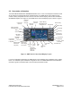
2.2 Description of Alteration The Garmin Model 400W Series GPS/WAAS Nav/Com unit is a 6 ¼ inch wide panel mounted unit with all the interface connections behind the instrument panel. The 400W Series units combine a large number of easily acceptable controls to use the color multi-function display, Nav and Com transceiver, GPS/WAAS navigator in a single unit. The 400W series control and display layout is shown in Figure 1.
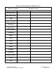
Table 1: Interfaced Equipment to 400W Series Unit 400W Series Unit Model ____________________ 400W Series unit P/N ____________________ Manufacturer / Model Location Main NAV Indicator VOR/ILS NAV Indicator EHSI CDI/HSI Source Selection Annunciator Audio Panel Encoding Altimeter or Blind Encoder Air Data Computer Altitude Serializer or Fuel/Air Data Weather Traffic Terrain DME Autopilot IRU/AHRS EFIS Display Multifuction Display 400W/500W Series Unit Crossfill Other 400W Series Rotorcraft Instructions fo
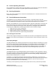
2.3 Control, Operating Information See the 400W Series Installation Manual (P/N 190-00356-02), listed under the reference documentation in paragraph 2.1 of this document, for system operation and self-test information. 2.4 Servicing Information None. In the event of system failure, troubleshoot the 400W Series unit in accordance with Section 2.6 Troubleshooting Information. 2.5 Periodic Maintenance Instructions The 400W Series units are designed to detect internal failure.
2.6 Troubleshooting Information If error indications are displayed on the 400W Series unit, consult the Troubleshooting section contained in the 400W Series Installation Manual (P/N 190-00356-02), listed under reference documentation in paragraph 2.1 of this document. The ‘400W Series Post-Installation Checkout Log’ in the rotorcraft permanent records includes the configuration information for the installation. (See Section 5 in the 400W Series Installation Manual (P/N 190-00356-02) for a sample Log). 2.
2.8 Diagrams Refer to the 400W Series Installation Manual, P/N 190-00356-02 and STC Rotorcraft Installation Supplement for 400W/500W Series, P/N 190-00357-22 (listed under reference documentation in section 2.1 of this document) for drawings applicable to this installation. Point to point wiring diagrams are in Appendix H of the 400W Series Installation Manual, and Appendix D of the STC Rotorcraft Installation Supplement for 400W/500W Series.
Table 3: Unit Location Information Part and Model Number C.G. Station (inches) Installed Location Description 400W Series Unit GPS Antenna Procedures and data required for wiring maintenance are described in the ‘Cable and Wiring Considerations’ section in the 400W Series Installation Manual (P/N 190-00356-02), listed under reference documentation in paragraph 2.1 of this document.
Table 4: 400W Series Power Input 14 VDC Input Connector 28 VDC Mode Typical Max Typical Max GPS 400W Main power P4001 -- 760mA 1.4A 410mA 700mA Main power P4001 -- 1.12A 2.5A 560mA 1.2A COM power P4002 RX 4mA 15mA 8mA 15mA TX 3.25A 6.0A 1.6A 3.0A GNC 420W GNC 420AW Main power P4001 -- 1.12A 2.5A 560mA 1.2A COM power P4002 RX N/A N/A 3mA 15mA TX N/A N/A 1.6A 3.0A GNS 430W Main power P4001 -- 1.60A 2.5A 800mA 1.
Table 5: Circuit Breaker Size and Placard Unit GPS 400W (P/N 011-01057-00, -10, -40, -50) GNC 420W (P/N 011-01058-00, -10, -40, -50) GNC 420W (P/N 011-01058-45) GNC 420AW (P/N 011-01059-00, -10, -40, -50) GNS 430W (P/N 011-01060-00, -10, -40, -50) GNS 430W (P/N 011-01060-45) GNS 430AW (P/N 011-01061-00, -10, -40, -50) 14 VDC Breaker Size 28 VDC Breaker Size Main (P4001) 5A 5A Main (P4001) 5A 5A COM (P4002) 10 A 5A Main (P4001) N/A 5A COM (P4002) N/A 5A Main (P4001) N/A 5A COM (P4002)
2.14 Additional Instructions None 2.15 Overhaul Period The system does not require overhaul at a specific time period. Power on self-test and continuous BIT will monitor the health of the 400W Series unit. If the unit indicates an internal failure, the unit may be removed and replaced. See troubleshooting section contained in the 400W Series Installation Manual, listed under reference documentation in paragraph 2.1 of this document. 2.
APPENDIX A 3.1 Wire Routing The following diagram depicts the wire harness and coax cable routing for the 400W Series unit(s) and antenna(s) throughout the rotorcraft structure: 400W Series Rotorcraft Instructions for Continued Airworthiness 190-00356-21 Rev.