
User Guide


190-00649-00 Rev. A
Garmin G1000 Pilot’s Guide for the Diamond DA42
3-1
EIS
SECTION 3 ENGINE INDICATION SYSTEM (EIS)
3.1 INTRODUCTION
NOTE: Refer to the Aircraft Flight Manual (AFM) for limitations.
The G1000 Engine Indication System (EIS) for the Diamond DA42 displays critical engine, electrical, fuel,
and other system parameters on the left side of the Multi Function Display (MFD) during normal operations. In
reversionary mode, the remaining display unit is re-configured to present Primary Flight Display (PFD) symbology
together with the EIS (refer to the System Overview for information about reversionary mode).
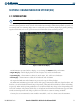
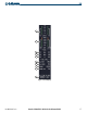
EIS
Figure 3-1 Multi Function Display
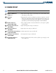
EIS information is presented in three displays, accessed using the
ENGINE
Softkey on the MFD:
• Engine Display – Default display, shows all critical engine, fuel, and electrical indicators
• System Display – Shows numeric readouts of critical engine, fuel, and electrical indicators
• Fuel Display – Shows numeric readouts of fuel indicators and calculations
The engine load indicator and tachometer are present at the top of all three displays.
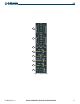
The DA42’s EIS instrument types include vertical slider gauges, horizontal bar indicators, digital readouts, and
slide bars. Green bands indicate normal ranges of operation; yellow and red bands indicate caution and warning,
respectively. When unsafe operating conditions occur, readouts and labels may change color corresponding to the
level of the condition. The pointers (labeled left, L, and right, R) on the horizontal bar indicators appear in white
to indicate normal operation and change to yellow or red to indicate caution or warning conditions.
If sensory data to an instrument becomes invalid or unavailable, a red “X” is shown across the instrument.