
User Guide


190-00649-00 Rev. A
Garmin G1000 Pilot’s Guide for the Diamond DA42
1-31
SYSTEM OVERVIEW
MFD DATA BAR FIELDS
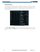
The MFD Data Bar Fields Box on the System Setup Page can be used to change the configuration of the
fields in the MFD Navigation Data Box. By default, the Navigation Data Box is set to display ground speed
(GS), distance to next waypoint (DIS), estimated time enroute (ETE), and enroute safe altitude (ESA). The
Navigation Data Box on the PFD is not affected.
Changing the information shown in an MFD Navigation Data Box field:
1) Select the System Setup Page.
2) Press the FMS Knob momentarily to activate the flashing cursor.
3) Turn the large FMS Knob to highlight the desired field number in the MFD Data Bar Fields Box.
4) Turn the small FMS Knob to highlight the desired selection from the data options list.
5) Press the ENT Key.
The following data may be selected for display in the four fields of the MFD Navigation Status Box.
• Bearing (BRG)
• Distance (DIS)
• Desired Track (DTK)
• Enroute Safe Altitude (ESA)
• Estimated Time of Arrival (ETA)
• Estimated Time Enroute (ETE)
• Ground Speed (GS)
• Minimum Safe Altitude (MSA)
• Track Angle Error (TKE)
• Track (TRK)
• Vertical Speed Required (VSR)
• Crosstrack Error (XTK)
GPS CDI
The GPS CDI Box on the System Setup Page allows the pilot to define the range for the on-screen course
deviation indicator (CDI). The range values represent full range deflection for the CDI to either side. The
default setting is ‘AUTO’. At this setting, leaving the departure airport the CDI range is set to 1.0 nm and
gradually ramps up to 5 nm beyond 30 nm from the departure airport. The CDI range is set to 5.0 nautical
miles during the enroute phase of flight. Within 30 nm of the destination airport, the CDI range gradually
ramps down to 1.0 nm (terminal area). During approach operations, the CDI range ramps down even
further to 0.3 nm. This transition normally occurs within 2.0 nm of the final approach fix (FAF).
If a lower CDI range setting is selected (i.e., 1.0 or 0.3 nm), the higher range settings are not selected
during any phase of flight. For example, if 1.0 nm is selected, the G1000 uses this for enroute and terminal
phases and ramps down to 0.3 nm during an approach. Note that the Receiver Autonomous Integrity
Monitoring (RAIM) protection limits follow the selected CDI range and corresponding flight phases.
The GPS CDI Box on the System Setup Page displays the following:
• Selected CDI range (auto, 5 nm, 1 nm, 0.3 nm)
• Current system CDI range (5 nm, 1 nm, 0.3 nm)
• ILS CDI capture mode setting (auto, manual)